Spark plug and manufacturing method therefor

a technology of spark plugs and manufacturing methods, applied in the field of spark plugs, can solve the problems of deterioration of ignition performance and high probability of abnormal discharge generation, and achieve the effects of enhancing sparking rate, effective prevention or reduction of abnormal discharge generation, and improving fuel ignition performan

Active Publication Date: 2011-08-11
NGK SPARK PLUG CO LTD
View PDF7 Cites 14 Cited by
  • Summary
  • Abstract
  • Description
  • Claims
  • Application Information

AI Technical Summary

Benefits of technology

[0027]As mentioned above, when the noble metal tip is laser-welded to the front end surface of the center electrode base metal in such a manner that laser welding is performed around the joint surface therebetween in the circumferential direction in excess of full circumference, the final end portion (end-point portion) of the weld bead assumes the form of an irregular projection or mound-like protrusion which is radially higher than the circumferentially other portion of the bead. When a spark plug is viewed in the axial direction from the front end of the noble metal tip, if the vertex of the protrusion exists on the straight line which connects the center of the noble metal tip and the circumferential center of the proximal end of the ground electrode, the distance between the protrusion and a portion of the ground electrode located toward the proximal end of the ground electrode becomes the shortest. Further, electric field is likely to concentrate at the protrusion, and thus an abnormal discharge is likely to be generated. Under the circumstances, when the dimensional relation A≦3G is established, where G is a spark gap (dimension) and A is the shortest gap (dimension) between the laser weld bead and a line drawn in parallel with the axis of the metallic shell along the inner surface of a proximal end portion of the ground electrode which faces the center electrode, an abnormal discharge is likely to be generated, particularly when the spark plug is mounted to a cylinder head in such an arrangement that a swirl flow flows in the direction from the center electrode to the proximal end of the ground electrode.
[0028]By contrast, the spark plug according to the invention described in claim 1 of the present application has the dimensional relation A≦3G. When the spark plug is viewed in the direction of the axis (the axis of the plug) from the front end of the noble metal tip, the vertex of a protrusion formed relatively high in the radial direction in the bead formed by circumferential laser welding does not exist on the straight line which connects the center of the noble metal tip and the circumferential center of the proximal end of the ground electrode, and is located circumferentially away from the straight line. Thus, the generation of abnormal discharge can be effectively prevented or reduced. As a result, the invention of the present application can enhance the sparking rate across the regular gap and thus can yield a quite important effect of improving fuel ignition performance. In view of prevention of the generation of abnormal discharge, preferably, the spark plug is assembled such that the vertex of a protrusion formed relatively high in the radial direction at the final end portion of a bead is located circumferentially away from the straight line to the greatest possible extent.
[0029]In assembly of such a spark plug, after the insulation member having the center electrode to which the noble metal tip is welded is inserted into the tubular metallic shell having the ground electrode at the front end thereof, it is good practice to make sure of the position of the vertex of the protrusion at the final end portion of a bead as viewed in the axial direction from the front end of the noble metal tip. That is, it is confirmed that, as viewed in such a manner, the vertex does not exist on the straight line which connects the center of the noble metal tip and the circumferential center of the proximal end of the ground electrode, but is located circumferentially away from the straight line. Specifically, the spark plug may be assembled as follows: the insulation member in which the center electrode, etc. are fixed is turned about the axis thereof by an appropriate angle within the metallic shell such that the vertex of the protrusion at the final end portion of the bead does not face a side toward the proximal end of the ground electrode, but preferably faces a side opposite the proximal end, and, in this condition, the insulation member is fixed to the metallic shell.
[0030]As mentioned above, a plurality of the protrusions are formed by laser welding from a plurality of directions by use of a plurality of laser welding machines. For example, a bead end protrusion is formed at two positions when laser irradiation is performed from two directions by use of two laser welding machines disposed at two circumferentially opposite positions as follows: the center electrode base metal is turned about the axis by, for example, 135 degrees, and, in the course of the turn, pulse welding is performed an appropriate number of times. In such a case, in the course of assembling a spark plug, positional relation may be determined as follows: as described in claim 2, neither of the vertexes of two protrusions existing in the circumferential direction exist on the straight line which connects the center of the noble metal tip and the circumferential center of the proximal end of the ground electrode, and the vertexes of the protrusions are located circumferentially away from the straight line. In this case, preferably, a bead portion formed relatively low in the radial direction between the two protrusions (preferably a circumferentially middle portion between the two protrusions or a portion located toward the circumferentially middle point between the two protrusions) exists on the straight line which connects the center of the noble metal tip and the circumferential center of the proximal end of the ground electrode. A protrusion is formed at three positions when laser irradiation is performed from three directions by use of three laser welding machines disposed at circumferentially equal angular intervals as follows: the center electrode base metal is turned about the axis by, for example, 80 degrees. In this case, preferably, a bead portion formed relatively low in the radial direction between any two protrusions (preferably a circumferentially middle portion between the two protrusions or a portion located toward the circumferentially middle point between the two protrusions) exists on the straight line which connects the center of the noble metal tip and the circumferential center of the proximal end of the ground electrode.
[0031]As mentioned above, the number of bead end protrusions varies with the number of directions from which laser welding is performed; i.e., with the number of weld beads. In the case where laser welding is performed circumferentially from a plurality of directions by use of a plurality of laser welding machines, the welding range (circumferentially angular range) is basically the same among the laser welding machines. Thus, the circumferential length of a bead depends on the number of laser welding machines to be used; usually, the circumferential length of a bead is obtained by dividing the outer circumference (full circumference) of the noble metal tip at equal angular intervals. Therefore, bead end protrusions are arranged at substantially equal circumferential intervals (angular intervals). Meanwhile, a center-runout-induced protrusion is not generated or is ignorable when positioning accuracy is high. Thus, even when a center-runout-induced protrusion is ignorable, in the case where a plurality of bead end protrusions exist, the protrusions may be positioned as follows: the positional relation of the protrusions with the proximal end of the ground electrode is, as described in claim 2, such that the vertexes of the protrusions are located circumferentially away from the aforementioned straight line.
[0032]Meanwhile, a center-runout-induced protrusion is generated irrespective of the number and position of bead end protrusions. Therefore, regardless of whether welding is performed from a single or a plurality of directions, two protrusions may be generated in proximity to each other. In such a case, the protrusions may be positioned as follows: as in the case of the invention described in claim 3, a bead portion corresponding to the maximum circumferential interval between two protrusions faces a side toward the proximal end of the ground electrode; and the vertexes of the two protrusions are located circumferentially away from the straight line which connects the center of the noble metal tip and the circumferential center of the proximal end of the ground electrode. The expression “a bead portion existing within the maximum circumferential interval between two protrusions faces a side toward the proximal end of the ground electrode” encompasses the case where the bead portion exists on the straight line which connects the center of the noble metal tip and the circumferential center of the proximal end of the ground electrode. More preferably, the vertexes of the two protrusions are located in circumferentially opposite directions from the straight line at substantially the same or the same interval (angle) from the straight line. That is, the positional relation in which the straight line passes a middle portion between the two vertexes is preferred.

Problems solved by technology

Particularly, in the case where a spark plug is used in a direct-injection engine in which an atmosphere within a combustion chamber is nonuniform or in an engine which involves an intensive swirl (air-fuel mixture flow), if the proximal end (root) of the ground electrode of the spark plug is located downstream of the air-fuel mixture flow, the generation of abnormal discharge is highly likely.
Such discharge or sparking across a gap other than the regular gap may fail to initiate regular ignition of fuel, with a resultant deterioration in combustion performance, and thus raises a problem of deterioration in ignition performance.

Method used


Image

  • Spark plug and manufacturing method therefor
  • Spark plug and manufacturing method therefor
  • Spark plug and manufacturing method therefor

Examples


Embodiment Construction

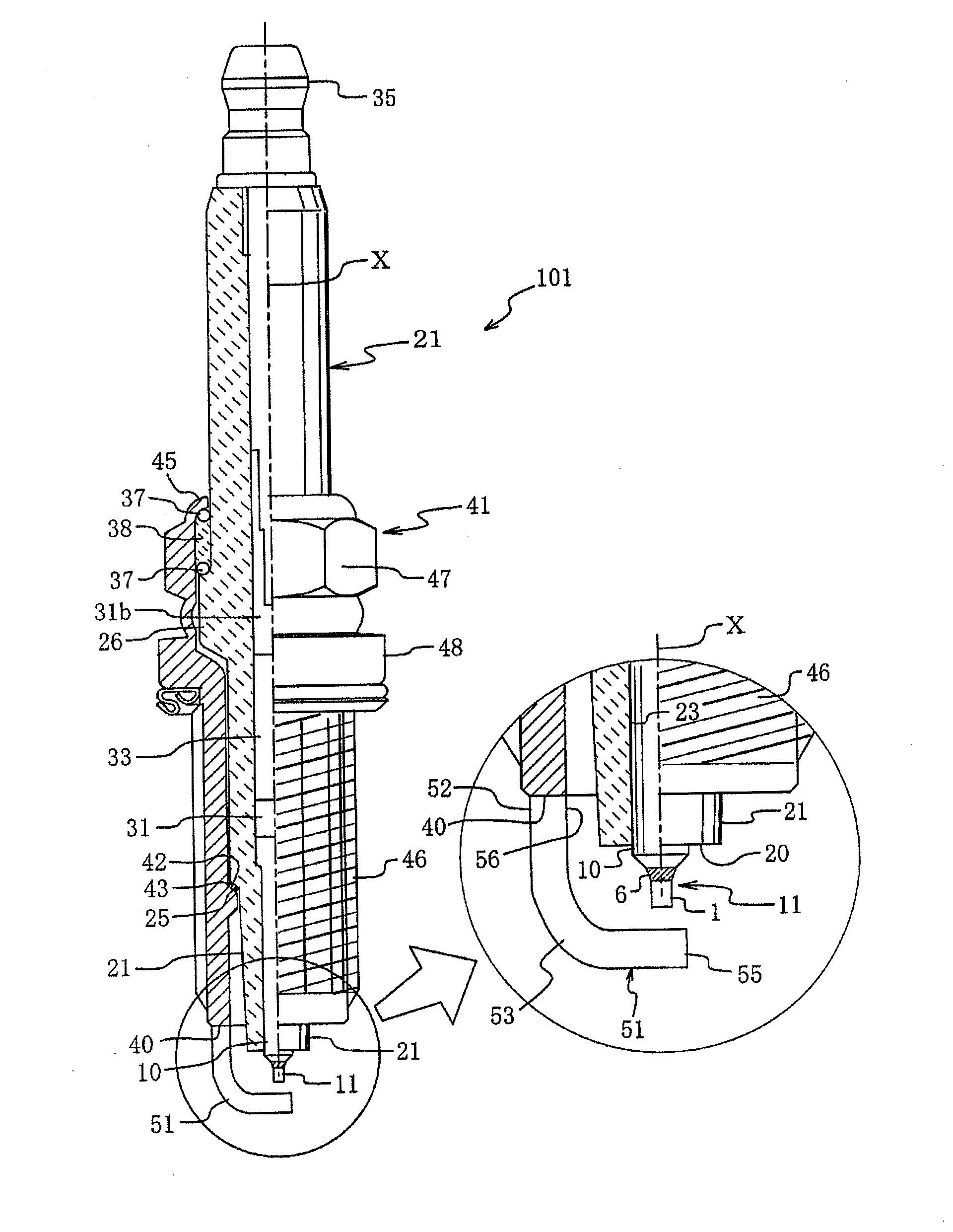
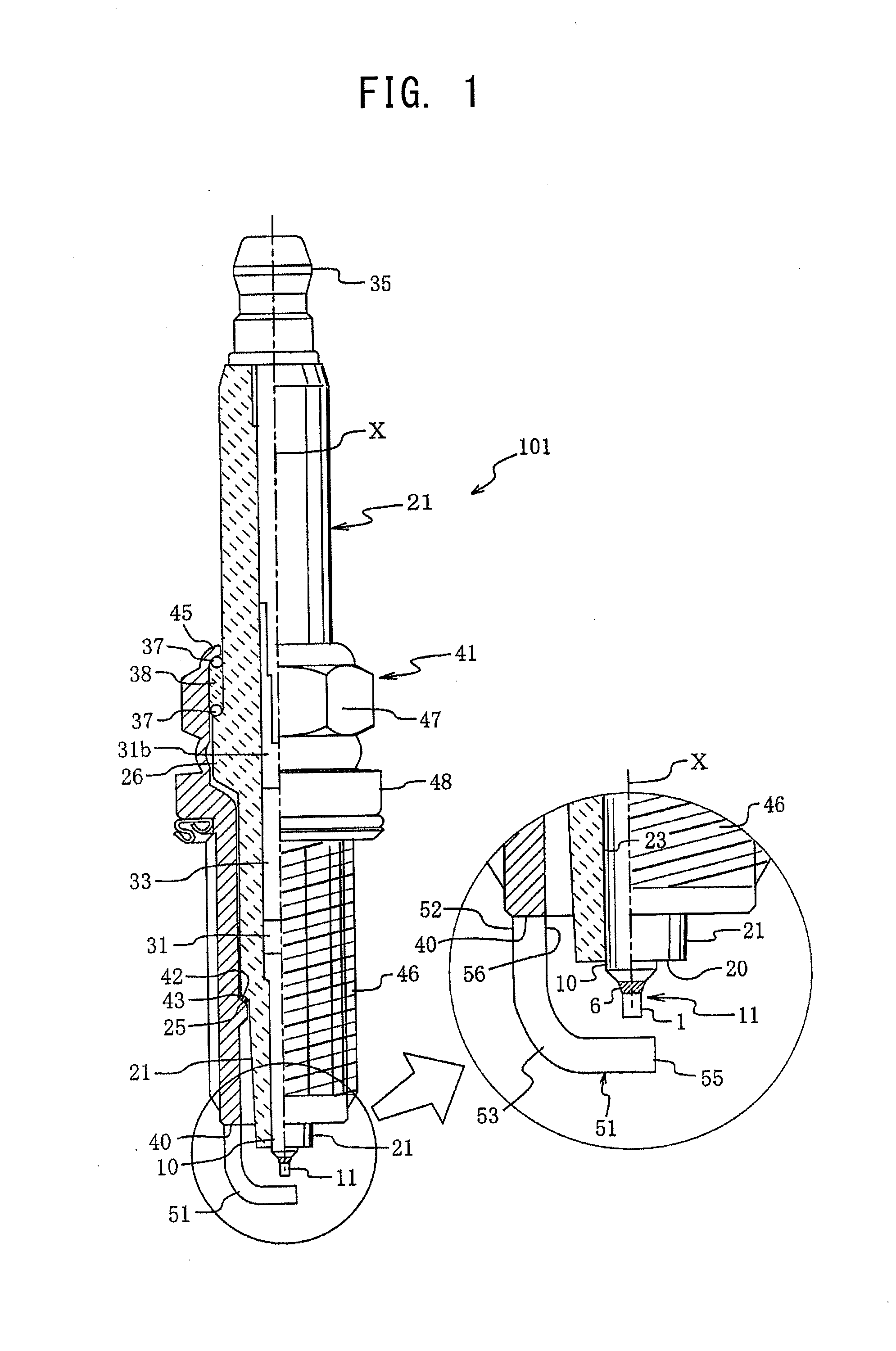
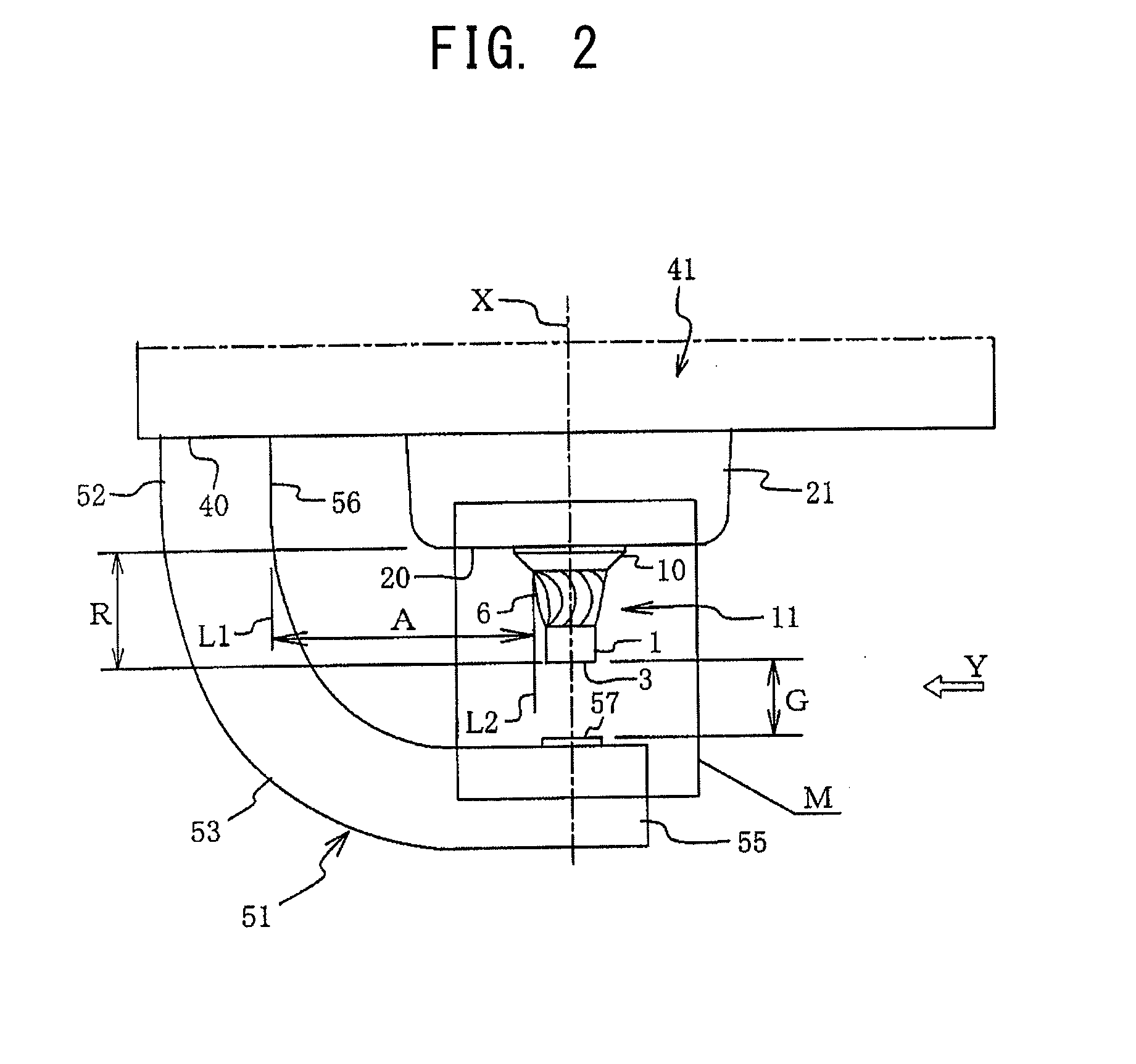
[0048]A spark plug according to an embodiment of the present invention will be described in detail with reference to FIGS. 1 to 6. First, the overall configuration of the spark plug of the present embodiment is described. Since the spark plug and its component members, such as a metallic shell and an insulation member (ceramic insulator), are similar in material and basic constitution to publicly known ones, description thereof is brief. FIG. 1 is a vertical half-sectional view for explaining the overall configuration of a spark plug 101, accompanied by an enlarged view showing essential portions (front end portion) of the spark plug 101. FIG. 2 is a further enlarged view showing the essential portions (front end portion) of the spark plug 101.

[0049]As shown in FIG. 1, the spark plug 101 of the present embodiment is composed primarily of a ceramic insulation member 21 which assumes the form of a hollow shaft and in which a center electrode 11 having a noble metal tip 1 welded theret...


PUM


Abstract

A spark plug in which the center electrode is formed by laser welding along the circumference of a joint surface between a center electrode base metal and a noble metal tip in excess of full circumference. When G represents a spark gap and A represents a shortest gap between a laser weld bead and a line drawn parallel with axis X, A≦3G. Straight lines S1 and S2 which connect the center of the noble metal tip 1 and the circumferential center of a proximal end 52 of the ground electrode 51 and vertex 8 of a protrusion 7 formed at a final end portion 6e of a bead 6 formed by circumferential laser welding, respectively, form an angle θ of 45 degrees. Since the protrusion 7 of the bead is the angle θ away from the ground electrode 51, an abnormal discharge is unlikely to be generated.

Description

TECHNICAL FIELD[0001]The present invention relates to a spark plug for use in an internal combustion engine and to a method for manufacturing the same.BACKGROUND ART[0002]There are proposed a large number of spark plugs used to provide ignition in an internal combustion engine, such as an automobile engine, and configured such that a noble metal tip which contains Pt, Ir, or the like as a main component is welded to an end of an electrode in order to enhance resistance to spark-induced erosion (refer to, for example, Patent Document 1). Particularly, use of the noble metal tip is very effective for a center electrode, since spark-induced erosion of the center electrode is large.[0003]Meanwhile, laser welding is the favored method of welding such a noble metal tip to a center electrode base metal in forming the center electrode. The general practice of laser welding is as follows. A noble metal tip (circular columnar body) is positioned and disposed, via one end surface thereof, at t...

Claims


Application Information

Patent Timeline
Patent Type & Authority Applications(United States)
IPC IPC(8): H01T13/20H01T21/02
CPCH01T13/20H01T21/02H01T13/39
Inventor KATO, TOMOAKI
Owner NGK SPARK PLUG CO LTD
Why Eureka
Try Eureka