Positioning system and method

a piezoelectric actuator and positioning system technology, applied in the field of positioning methods and systems, can solve the problems of mechanical resonance, affecting the positioning accuracy, scanning speed and stability, and severely limited piezoelectric actuator positioning accuracy, etc., to improve the closed-loop response of the system, improve the accuracy of positioning and positioning, and improve the effect of tracking and damping performan

Inactive Publication Date: 2011-08-11
ELEKTRON TECH UK
View PDF49 Cites 31 Cited by
  • Summary
  • Abstract
  • Description
  • Claims
  • Application Information

AI Technical Summary

Benefits of technology

[0080]Preferably, the method comprises the step of adding a feedforward input to the feedback loop to improve the closed-loop response of the system.
[0081]Preferably, the system is a nanopositioning system. That is, the system enables the precise motion and positioning of the object on the nano-scale.
[0082]In the invention, measurement of actuator load force is used as a feedback variable for both tracking (position) and/or damping control in the feedback loop. Advantageous

Problems solved by technology

In practice, however, the positioning accuracy of piezoelectric actuators is severely limited by hysteresis over relatively large displacements and creep at low frequencies.
Another difficulty with nanopositioning systems is mechanical resonance, which arises from the platform mass interacting with the finite stiffness of the support flexures, mechanical linkages and/or actuator.
Mechanical resonance introduces unwanted vibrations into the nanopositioning system, thus affecting its positioning accuracy, scanning speed and stability.
This necessarily restricts the closed-loop bandwidth of the nanopositioning system.
However, the bandwidth of integral tracking control is severely limited by the presence of highly resonan

Method used


Image

  • Positioning system and method
  • Positioning system and method
  • Positioning system and method

Examples


Embodiment Construction

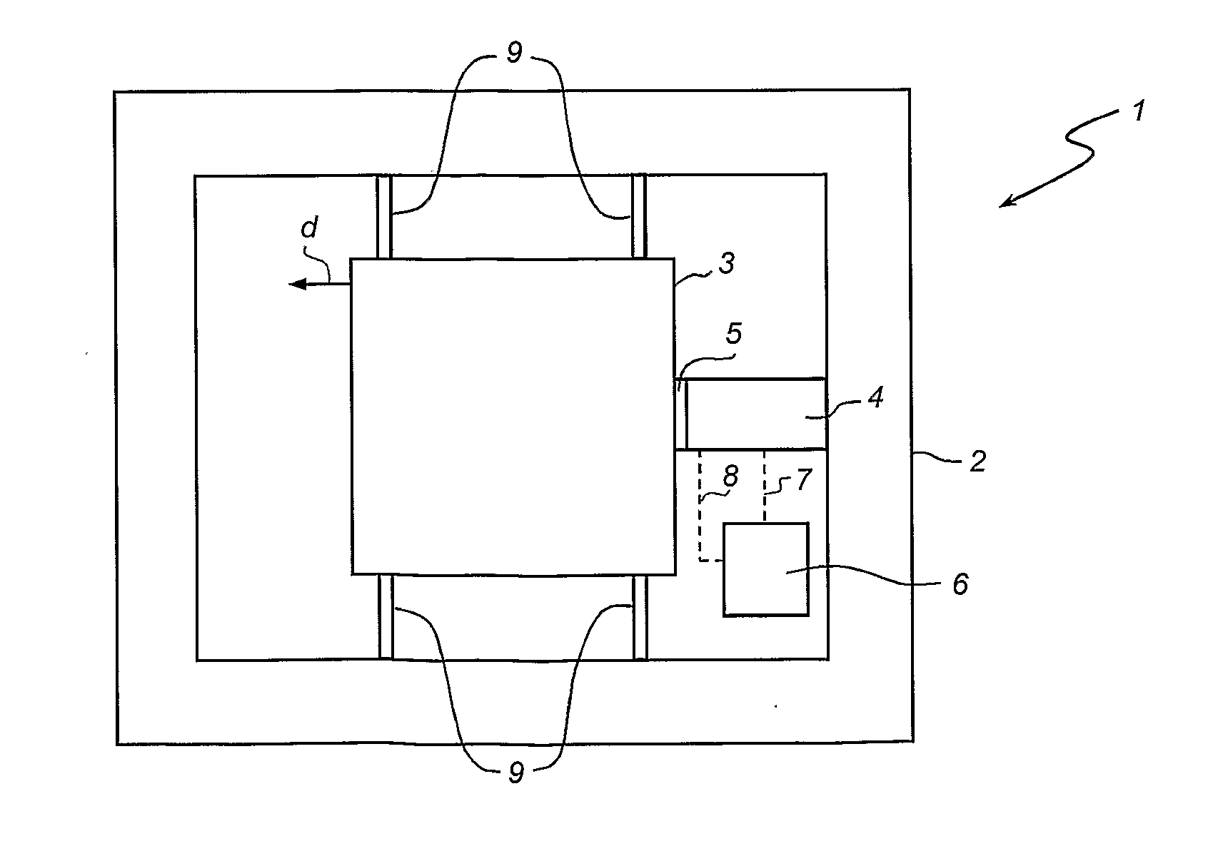
[0111]A preferred application of the invention is in the field of nanopositioning systems, apparatuses and methods. Such systems and apparatuses typically have a fixed base with a movable platform or stage, with guiding flexures and / or mechanical linkages so as to constrain the movement of the platform or stage to a single degree of freedom. The object is mounted to or located on the platform or stage and the apparatus moves the platform to precisely position the object. Additional flexures and / or mechanical linkages may also be connected to the platform so that the platform can have multiple degrees of freedom, and can be constrained to move in a single degree of freedom at any one time.

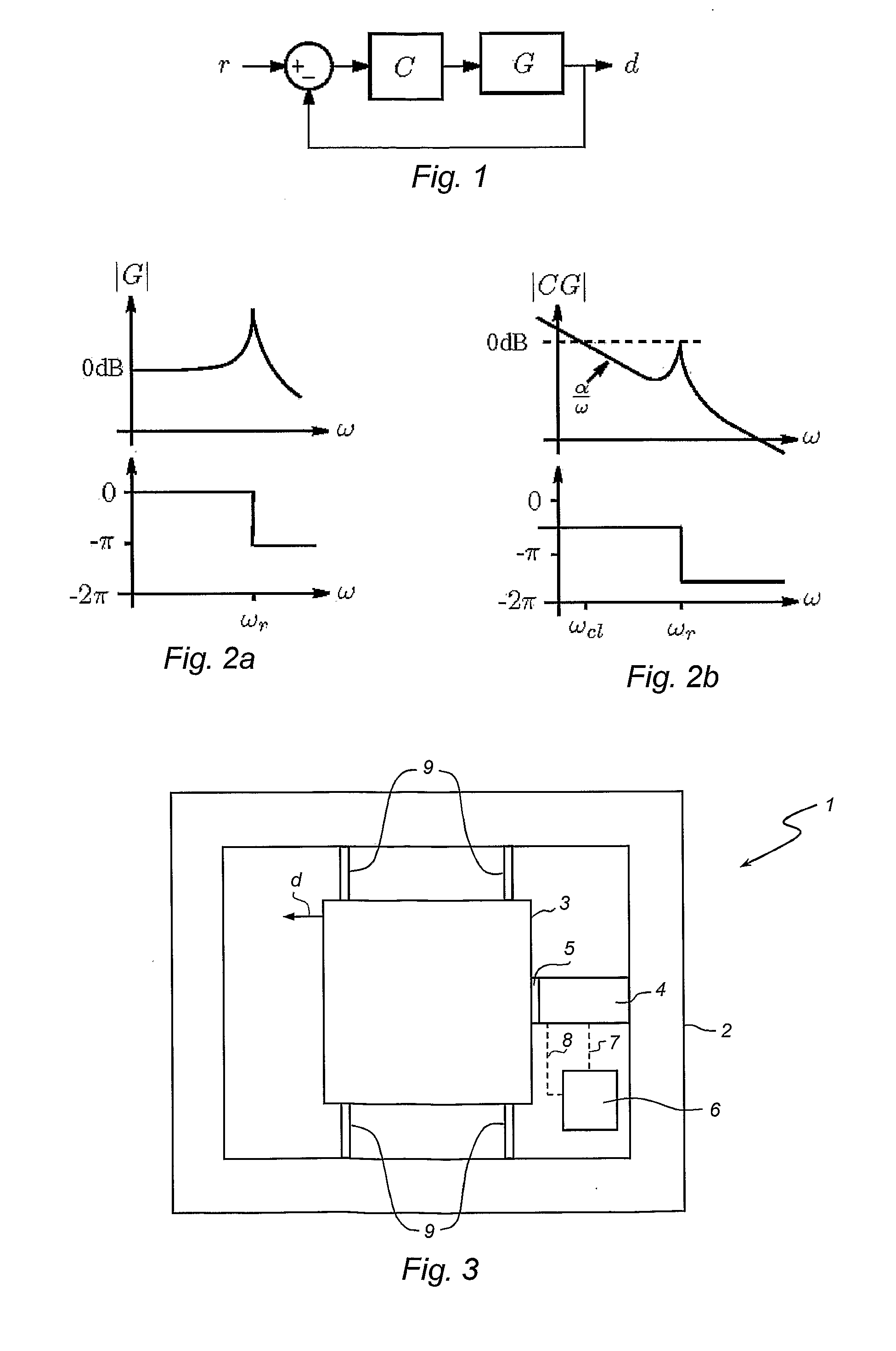
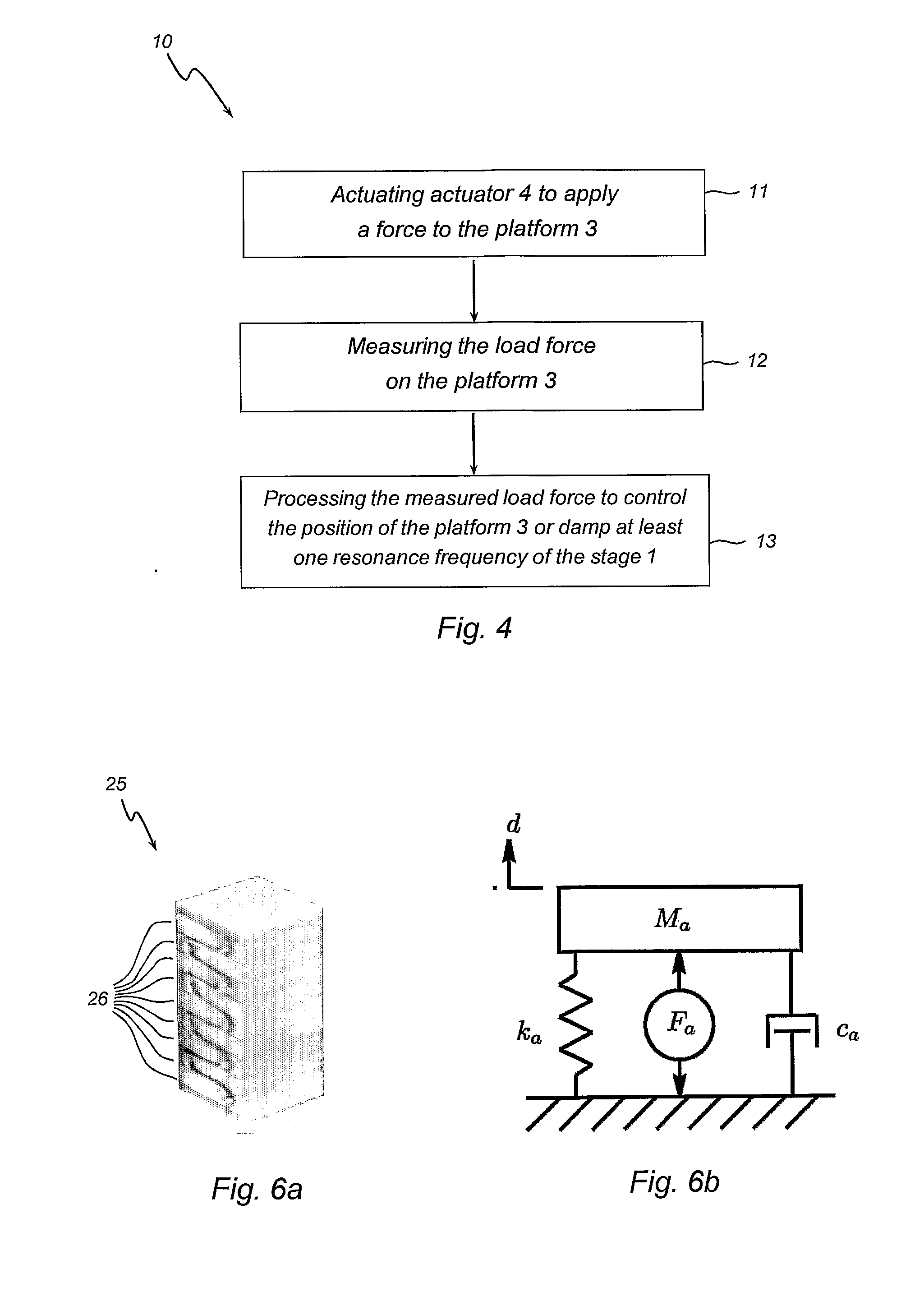
[0112]As discussed above, such nanopositioning systems suffer from limitations due to hysteresis, creep and mechanical resonance. In particular, mechanical resonance limits the operation of the nanopositioning systems in terms of its positioning accuracy, speed and stability.

[0113]As the lowest reso...


PUM


Abstract

A system for positioning an object, having a fixed base, a support for the object, an actuator for applying a force to displace the support relative to the fixed base, a sensor for measuring the load force on the support, and a controller for processing the measured load force to control the position of the support and/or damp at least one resonance frequency of the system. A method of controlling the system is also provided.

Description

FIELD OF THE INVENTION[0001]The present invention relates to a positioning method and system and in particular a method and system for nanopositioning apparatuses.[0002]The invention has been developed primarily for use in a nanopositioning system or apparatus, and will be described hereinafter with reference to this application. However, it will be appreciated that the invention is not limited to this particular field of use. In particular, it is contemplated that the invention is also applicable to positioning systems, apparatuses and methods where precise and accurate displacements of an object mounted in the positioning system or to a positioning apparatus are required.BACKGROUND TO THE INVENTION[0003]The following discussion of the prior art is intended to present the invention in an appropriate technical context and allow its significance to be properly appreciated. Unless clearly indicated to the contrary, however, reference to any prior art in this specification should not b...

Claims


Application Information

Patent Timeline
IPC IPC(8): G05B5/01
CPCB82Y35/00G01Q10/065G05B2219/49281G05B19/235G05B2219/49279G03F7/70725B23Q15/00G03F7/20G03F9/00G12B5/00G01Q10/00
Inventor FLEMING, ANDREW
Owner ELEKTRON TECH UK
Why Eureka
Try Eureka