Stacked flyback converter with independent current loop control

a current loop control and converter technology, applied in the direction of dc-dc conversion, power conversion systems, instruments, etc., can solve the problems of large stress on semiconductor based switching devices, heavy demands on the magnetic design of transformers, and difficult to make a wide input range converter

Inactive Publication Date: 2011-08-11
ABB INC
View PDF4 Cites 21 Cited by
  • Summary
  • Abstract
  • Description
  • Claims
  • Application Information

AI Technical Summary

Problems solved by technology

This requirement can put heavy demands on the magnetic design (of the transformer) as well as large stresses on the semiconductor based switching devices.
Though the traditional stacked flyback converter has proven to be a useful topology, drawbacks persist.
For example, it is difficult to make a wide input range converter (e.g. 200V-1000V DC input) having enough duty cycle out of the control I.C to generate the required output voltage across the whole range.
In such a situation, control can become unstable.

Method used


Image

  • Stacked flyback converter with independent current loop control
  • Stacked flyback converter with independent current loop control
  • Stacked flyback converter with independent current loop control

Examples


Embodiment Construction

[0015]It should be noted that in the detailed description that follows, identical or similar components have the same reference numerals, regardless of whether they are shown in different embodiments of the present invention. It should also be noted that in order to clearly and concisely disclose the present invention, the drawings may not necessarily be to scale and certain features of the invention may be shown in somewhat schematic form.

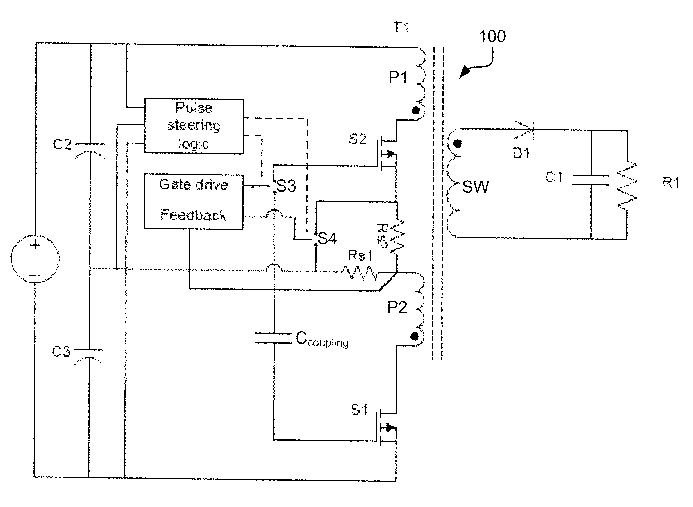
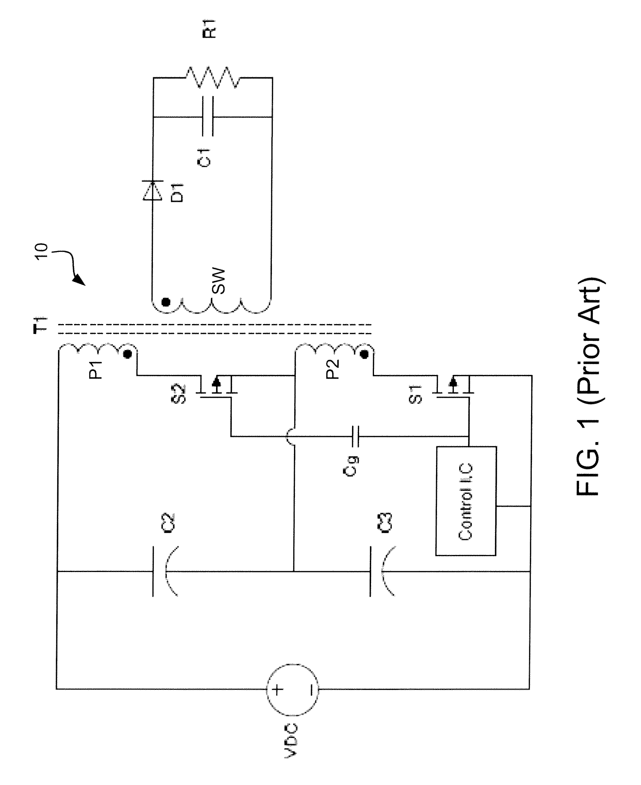
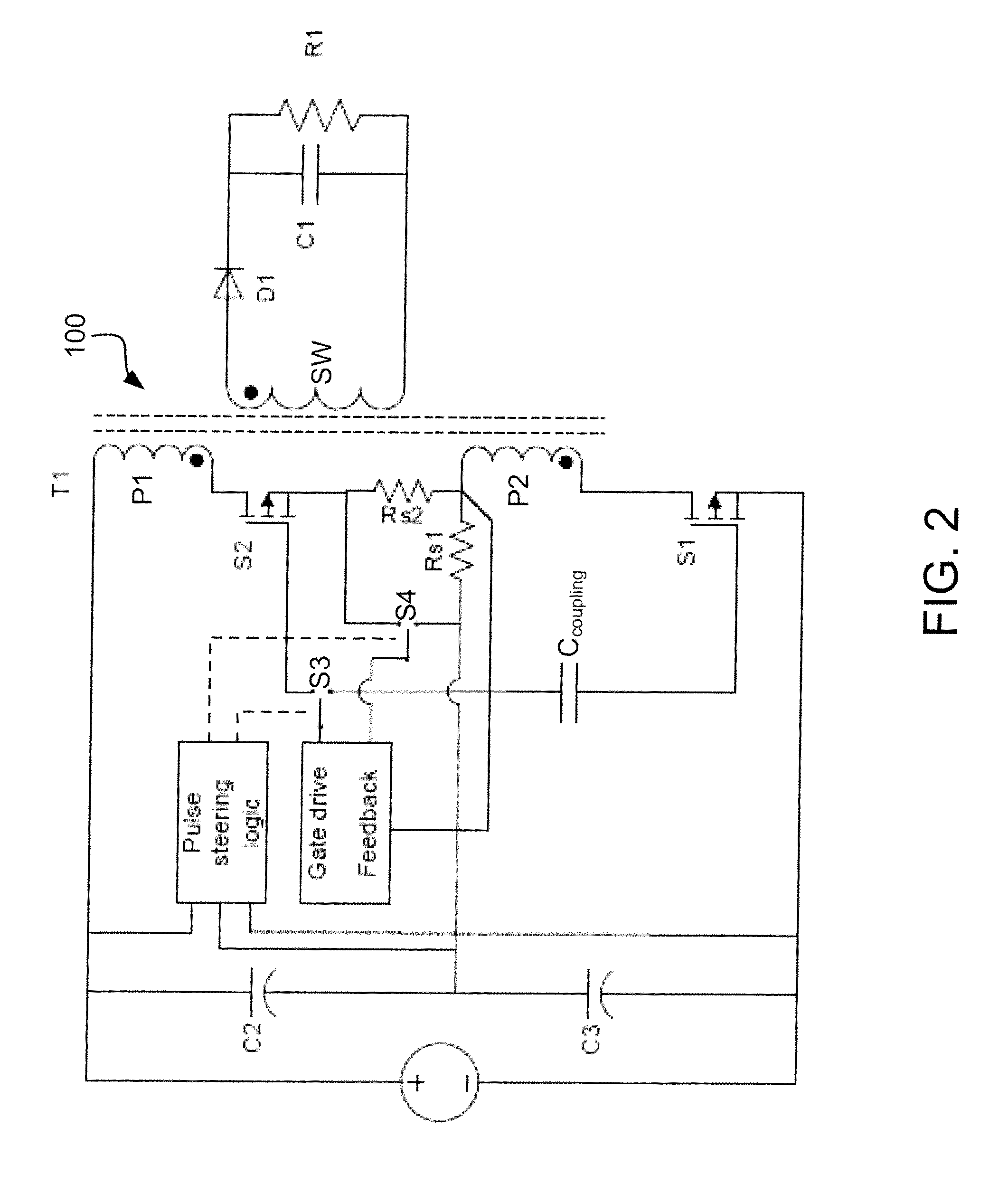
[0016]With reference now to FIG. 2, a stacked flyback converter according to the present invention is shown and generally indicated by the numeral 100. As with the configuration shown in FIG. 1, a DC power source VDC provides power to the system. It should be appreciated that, though not shown in the drawing, an AC bridge rectifier could be provided to convert an AC input voltage from a supply network to the DC input voltage to the converter. Capacitors C2 and C3 have the same rated capacitance, and are connected in series across the DC input volt...


PUM


Abstract

A voltage converter includes a transformer with a pair of primary coils and a secondary coil. The converter has a DC input and a capacitor bank, having a pair of capacitors, is connected across the DC input. A switch is associated with each primary coil. A gate drive feedback module outputs a pulse width modulated signal to drive either the first or second primary coil. A gate drive switch has as an input the pulse width modulated signal and outputs to the first second switch. A pulse steering logic module determines which of the first or second capacitors has a higher voltage and controls the gate drive switch to direct the pulse width modulated signal in response thereto.

Description

BACKGROUND[0001]Microprocessor control of today's electronic equipment requires efficient means of supplying power. Most line operated equipment utilizes some form of switching power supply to deliver control power to load circuits. Generally, a switching power supply rapidly switches a power transistor between a saturation state (full on) and cutoff (completely off) state, with a variable duty cycle whose average is the desired output voltage. In the North American market, typical three phase industrial power can range from about 208 VAC to about 575 VAC. In Europe, line voltages can be even higher, in some regions reaching 690 VAC.[0002]Taking advantage of the economic benefits of a high volume product requires a power supply to be designed with the largest available input voltage range while still maintaining accurate control of the output voltages. This requirement can put heavy demands on the magnetic design (of the transformer) as well as large stresses on the semiconductor ba...

Claims


Application Information

Patent Timeline
Patent Type & Authority Applications(United States)
IPC IPC(8): H02M3/335
CPCH02M3/33569
Inventor TRUETTNER, DONALD J.GOKHALE, KALYAN P.
Owner ABB INC
Why Eureka
Try Eureka