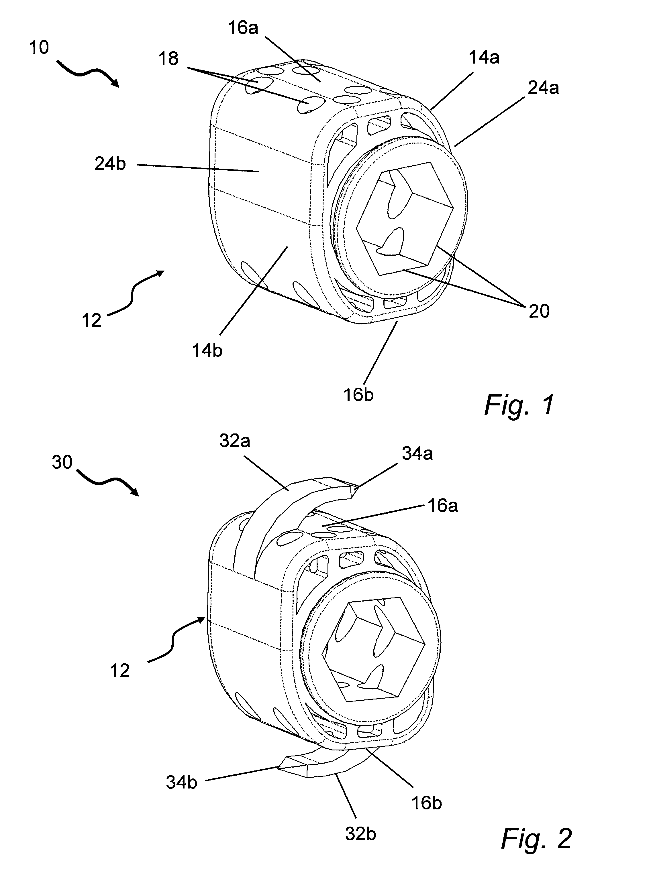
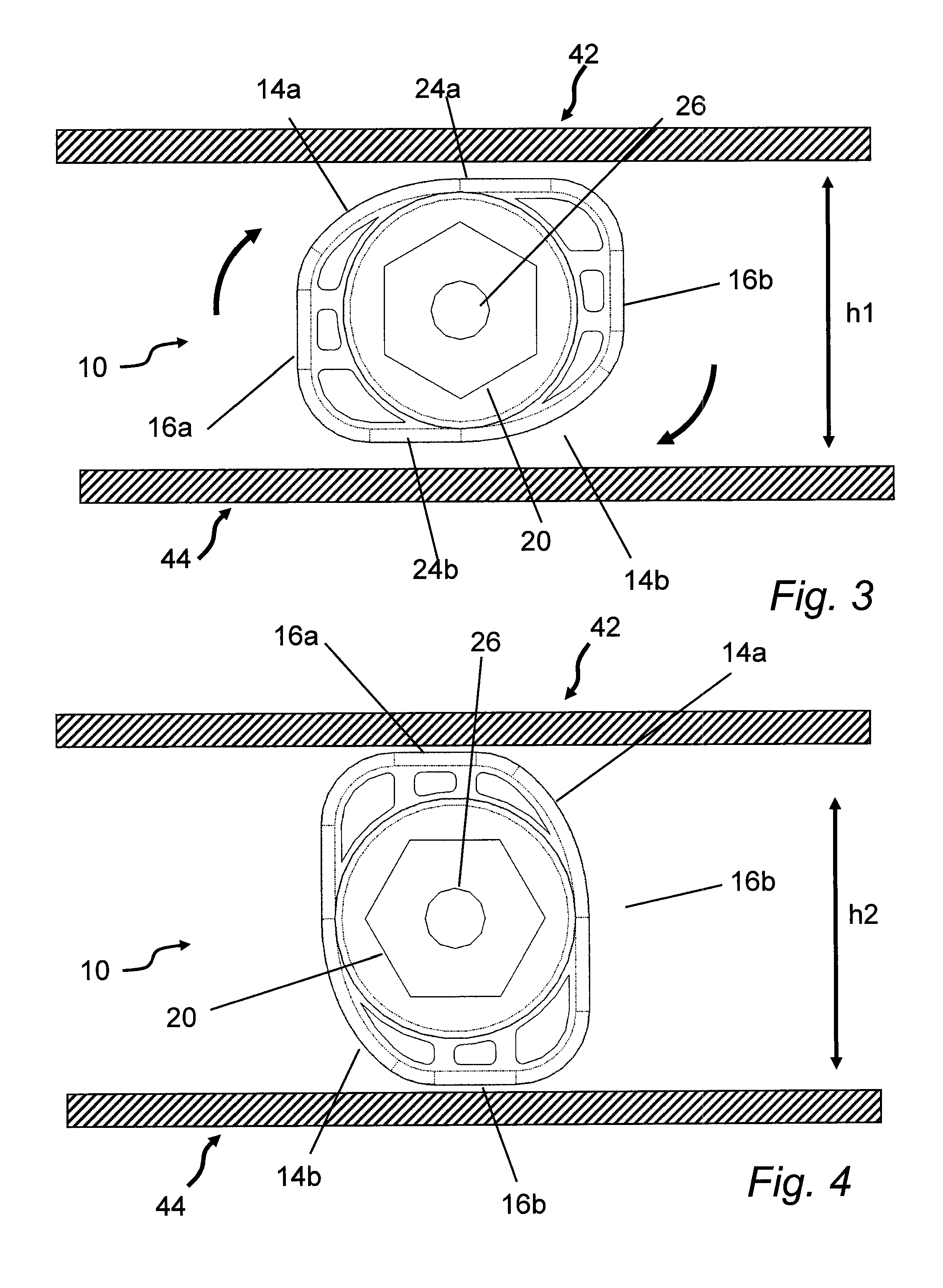
[0015]1) A single rotating cam cage is described. The cam is oblong / eccentric in shape, allowing it to be placed in a flat dimension and then, once placed in the interbody space, rotated to secure it in place and also to provide lift to the interbody space. The single rotating cam cage has a number of fenestrations along its length. Bone graft material is meant to be placed into the central portion of this rotating fenestrated cam allowing for bony fusion. The length, height, and width of this cam can vary as appropriate for the interbody space. This rotating cam cage may also have fixation anchors integrated into the external body of the cam cage which protrude from the body and have pointed ends to provide additional fixation and immobility of the cam once deployed. The rotating cam cage may be constructed as a tapered or “stepped” device (thicker posteriorly) to aid in posterior elevation and lift; this aids in indirect decompression of
spinal canal and neural foraminal stenoses. In addition, this device (especially with fixation anchors) can be used as a reduction device for spondylolithesis (subluxation). By placing this device(s) in a more horizontal fashion, it can result in the fixation anchors being able to move one
vertebral body with respect to the adjacent
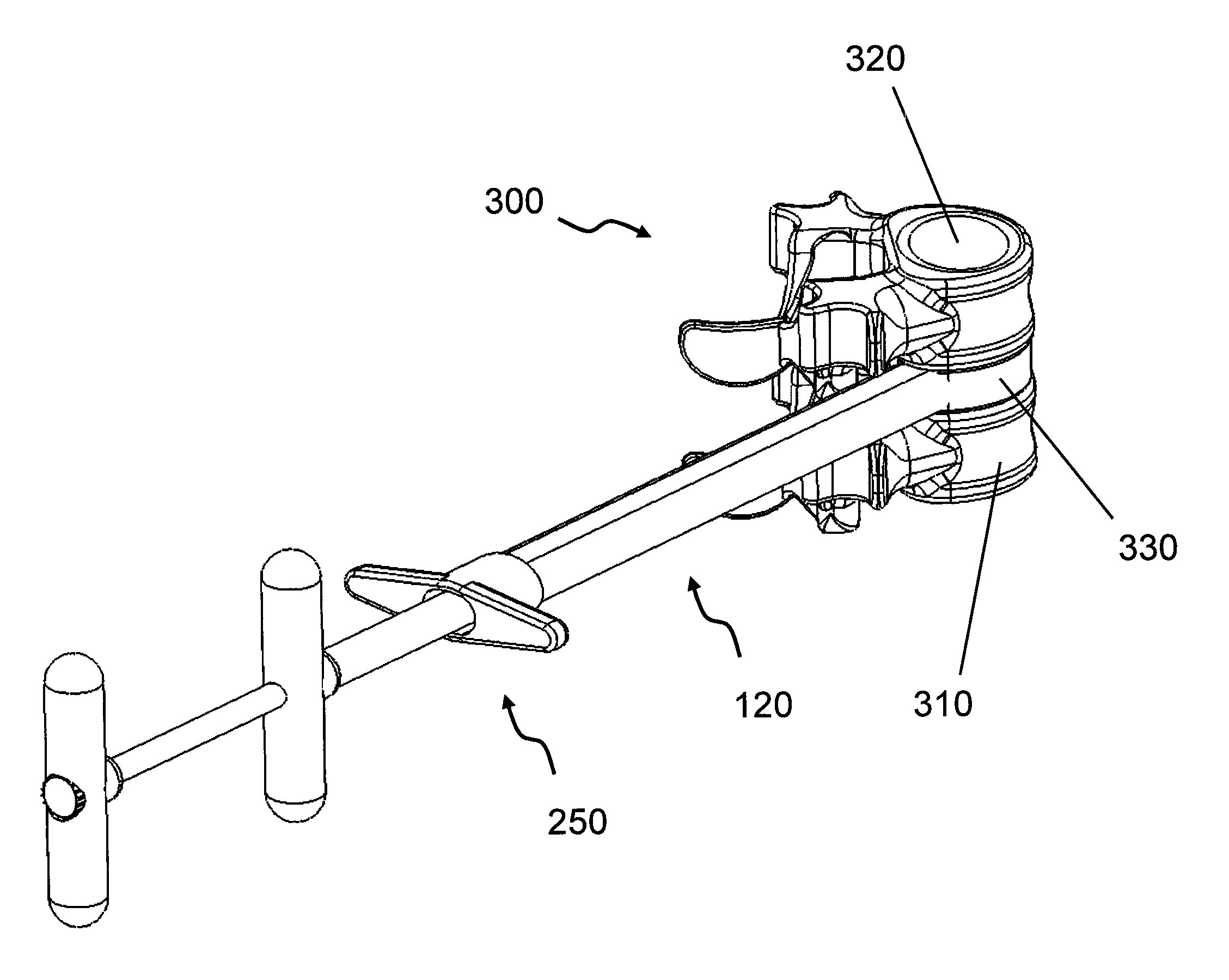
vertebral body, improving alignment and helping to reduce subluxation (spondylolithesis). With either the cam shape itself wedged into the bone, or the rotating cam with anchors wedged into the bone, immediate mechanical interbody fixation can be achieved; the addition of bone graft allows for long-term bony fusion. A unique delivery tool for percutaneously delivering the rotating cam cage to the spine, comprising a delivery sheath and rotating (turning) member, is also described. The delivery tool engages with a delivery tool engagement feature in the cam to rotate the cam cage. If considered necessary, the cam can be further anchored into the endplates using the
percutaneous, off-angle bone stapling / nailing device. Both the delivery tool and the cam cage may be cannulated for
insertion over a guide pin or wire.
[0027]6) A
Percutaneous Off-Angle Bone Stapling / Nailing Device is provided. The bone stapling / nailing device is comprised of a guide body
assembly, a ram (driver), a
cartridge, and the fixation device (e.g., staples, nails or brads). The guide body
assembly is comprised of a rigid guide body, a flexible guide, and a
cartridge adapter. The flexibility of the guide, which is curved to direct the
cartridge radially, allows the distal end of the guide body
assembly to deflect during
insertion, allowing for off-angle fixation
device placement and removal. This device is designed to percutaneously place curved staples, nails, brads, or other types of anchoring / fixation devices, to provide anchor fixation or bone union. Exemplary features of this off-angle, percutaneous staple / nail / brad placement device include a curved staple or nail or brad, various staple, nail or brad shapes (standard wire staple design, barbed points, brad points,
metal side fletching anchors, etc), and a flexible staple neck, to allow for fixation devices to be deployed off-axis to the delivery tool. The staples, nails or brads can be in a cartridge (new staple, nail or brad snapped in each time) or the staple / nail / brad can be loaded through the end. The cartridge may have various configurations (e.g.,
single use, reloadable, multiple staples / nails / brads). There can be multiple staples, nails or brads (like a regular staple or
nail gun). The percutaneous off-angle fixation staple / nail / brad anchor delivery tool driver can be driven forward with different driving forces: it can be tapped with a hammer (manual), hit with a single forcible blow (like a standard staple or
nail gun), or hit multiple times with smaller blows (
impact hammer). Alternatively, the driver can be power driven (pneumatic, electric, etc.) for single hard blow, or a powered
impact hammer type device that generates a high repetition of smaller blows. The fixation staple anchor delivery tool may have a notch on its distal tip to locate and center over a device (e.g. wire coil of a spring cage). The off-angle design and small size allow the placement of fixation staples or nails at an angle different from the
device placement direction into a bone. Thus, this allows “sideways” placement of staples or nails into a bone. The flexible neck of the delivery tool allows the end of the staple or nail cartridge to deflect radially to contact the spring cage wire; another deployment device can be added to help force the staple out of the delivery tool. If smaller staples are used, two staples can be deployed at the same time, 180 degrees opposed (one in each end plate). The fixation staple anchor and delivery tool can be made in various sizes and can be used for other bony neurologic, orthopedic, and interventional procedures.

