
Patent for a personal transportation network-ptn

Inactive Publication Date: 2011-08-11
JORGENSEN ARNE ROY
View PDF2 Cites 21 Cited by
  • Summary
  • Abstract
  • Description
  • Claims
  • Application Information

AI Technical Summary

Benefits of technology

[0003]The car like vehicle is small and only large enough to accommodate no more than four individuals leaving the same place at the same time going to the same destination such as a small family of three and no more than four with their luggage or two people in wheelchairs and one person in a seat or two people with two bicycles. Since the majority trips are for only one or two people, a vehicle that serves these basic needs will be most economical allowing a smaller lightweight pathway more for a rather continuous flow of traffic rather than a large heavyweight roadway designed to accommodate a large number of passengers in a massive vehicle that runs intermittently. The pollution free cars are electrically driven from an external arm on each side of the car that can engage power rails on one or the other side depending on the track roadway that is being traveled. The external arms also serve as a redundant steering control especially in a switch area. Its' path is preprogrammed through a maze of rail paths to arrive at its' destination without stopping. On its' path it is programmed to fit into other traffic during the trip and maintain the speed setting for that lane of traffic. In other words when the vehicle is to enter a high speed straight run, it must automatically sense the opening in traffic well ahead of time and automatically time it's acceleration so that it reaches the new speed while entering the switch and blend into a space between groups in traffic. Cars on the high speed pathway are electronically coupled to each other and have redundant communication to all the other cars on that line and travel in groups of 2 to 20 vehicles to provide space between groups for other cars entering the line. The space established for electronic coupling is established by the time it takes to electronically receive and react to a signal from any one of the cars on the line. This can be just milliseconds so the minimum coupling space is determined by that time and the operating speed so the coupling distance which can be around one foot at speeds up to 100 mph. The distance measurement between cars is either a Doppler radar or laser distance measuring system with an accuracy of less than 1″. What makes this network cost effective relative to cars and trains is the rapid throughput capacity relative to the cost of the guide rails and the constant utilization of all cars in the network and the distribution of cars in the network to always be available at any station within less than one minute.
[0004]In order to change direction from a high speed line, the car must switch off to a lower speed rail to enter a curve in a new direction and again switch into another high speed lane in the new direction at a new elevation. If the network is designed for the cars traveling on the right side of the street all turns are left turns. This allows for a larger radius and higher speed in the turns over the normal streets. Likewise north and south bound lanes cross west and east bound lanes at different elevations.
[0006]In order to obtain efficient economical through put on local, medium and high speed rails, all lines are assigned a speed setting in which cars entering the line come up to full speed when entering a switch and fit between cars traveling at the set speed. Local speeds in the one square mile neighborhoods travel at about 25 MPH and can switch to main streets that run at higher speeds of either 40 MPM or 50 MPH depending on the width of the streets that can accommodate a radius appropriate for the turning speed. The radius of each curve is based on a comfort level to the passengers which appears to be about 0.18 G through the curve. As needed when demand is there, the expressways can be used for high speed lanes that can operate at speeds up to 100 MPH. These require long turn on and exit lanes so the cars reach that speed before blending into the elevated pathway traffic. Continuous flow of cars over one lane of an elevated transportation network can transport more people than six or seven lanes of expressway traffic and therefore much more cost effective than building additional expressway lanes.
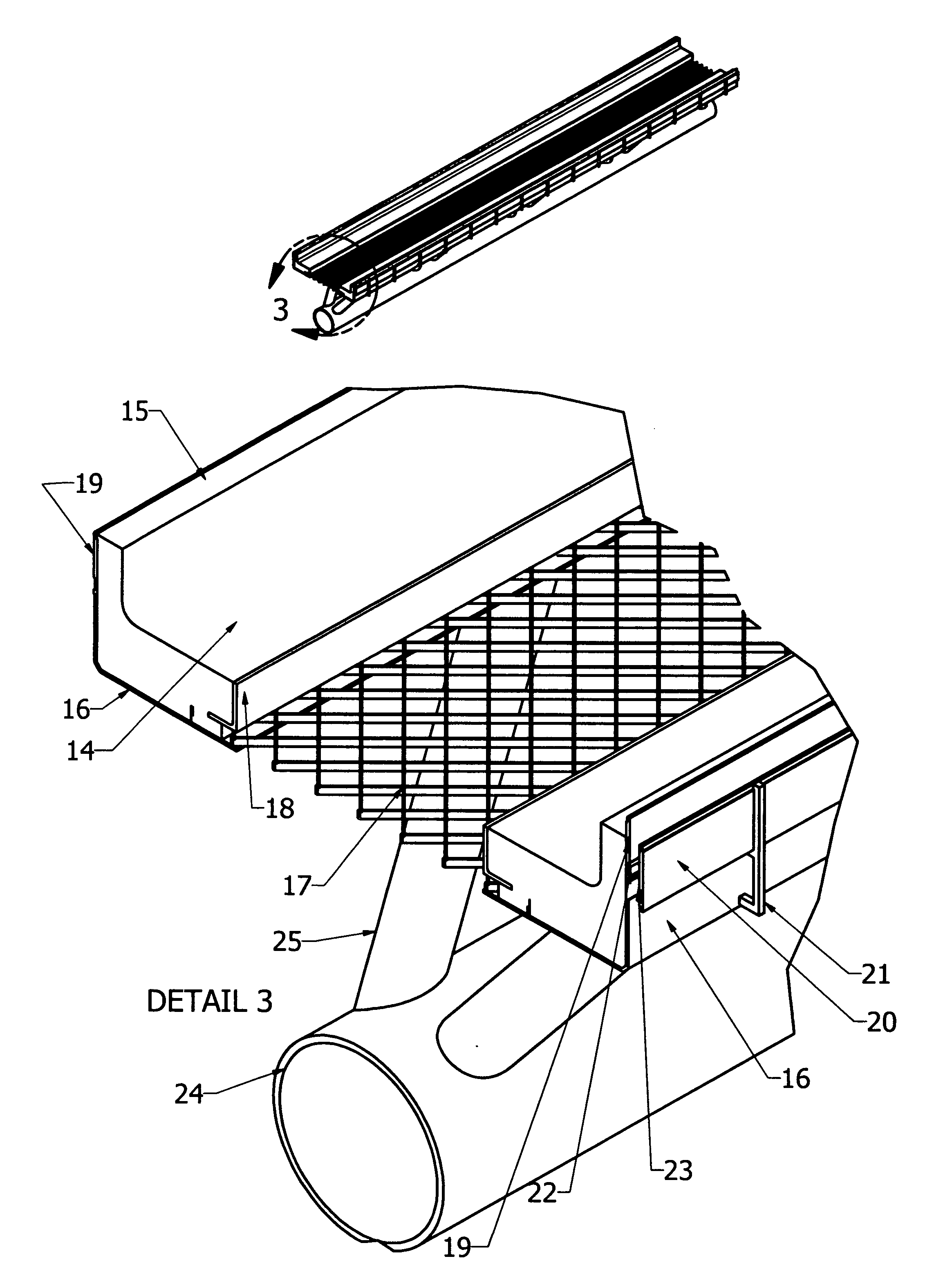
[0008]The cars each have four drive supporting wheels that run on two ribbon paths with an open area between the two smooth concrete ribbons with no interruptions in the driving path. These ribbons are tied together with bracing consisting of open grating for snow to pass through and also provide stability and side strength to the structure. Outboard of each ribbon is a vertical fence encompassing the car path and outboard of one of the fences are electrical power take off guide rails that also provide redundant steering control in addition to the primary Doppler or Laser controlled steering.

Problems solved by technology

Present transportation in a large city is very slow unless you live near a train that has the right away and takes you to where you are going without any transfers.
But in congested city traffic congestion during rush hour your driving time can double or treble.
Narrow streets are impractical to widen and expressway have long lines of stopped traffic just waiting to get on or off the expressways.
This is impractical if large throughputs of passengers going to different places are going to maximize use of an elevated roadway.

Method used


Image

  • Patent for a personal transportation network-ptn
  • Patent for a personal transportation network-ptn
  • Patent for a personal transportation network-ptn

Examples


Embodiment Construction

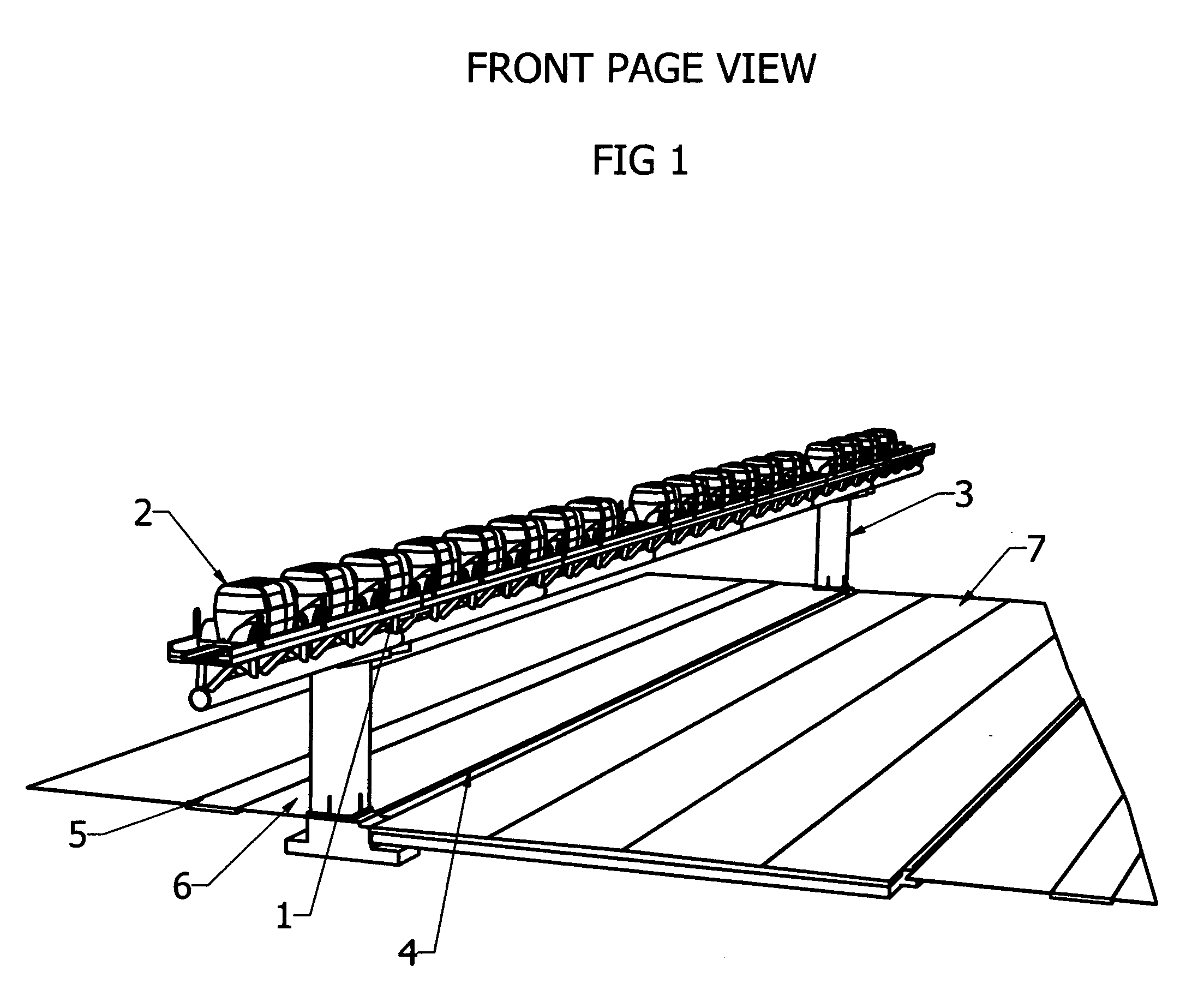
[0028]Referring to FIG. 1 showing an elevated ribbon pathway 1 with cars 2 in groups of 4 to 16 riding in the dual ribbon pathway 1 and supported by a concrete or metal structure 3 located in the parkway 6 between the curb 4 and the sidewalk 5 of a local street with the pathway 1 overhanging the inner lane of the street 7. The pathway 1 is a prefabricated structure about 40 feet long that can be quickly put together in 200 foot increments and positioned on supports 3 located at about 200 foot increments.

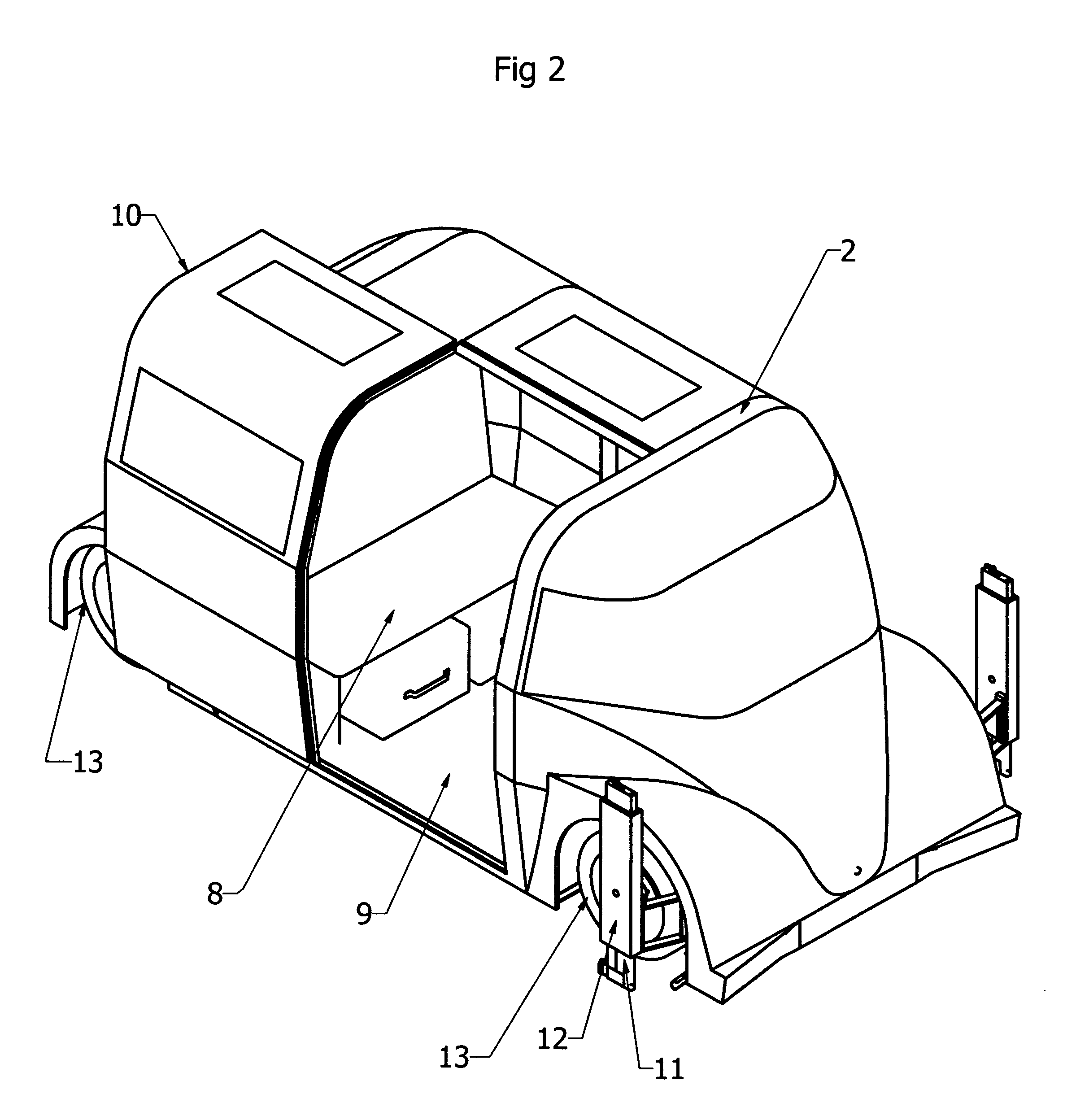
[0029]Referring to FIG. 2 showing an electrically powered car 2 with one of two sliding doors 10 opened for a better view of the interior consists of one full size seat 8 that sits three across and a small jump seat 8 in the front facing rearward that can fit two small toddlers. The space under the seat 8 is large enough to hold two large suit cases and the jump seat 8 has room enough for one smaller suitcase that fits sideways. The floor space 9 is large enough to accommodate two wh...


PUM


Abstract

This invention generally relates to an elevated transportation network run on electricity with personalized cars that can automatically transport passengers anywhere in a large city or densely populated metropolitan area served by the system without stopping on the way to the final destination. The cars travel on two continuous concrete ribbons with no bumps or cutouts crossing the tire path during switching or on the straight away. The travel path is a combination of central routing and individual car communications with car automatic steering and distance control. The personalized transportation concept can also apply to high speed intercity transportation allowing instant available transportation without intermediate time consuming stops.

Description

SUMMARY OF INVENTION[0001]Present transportation in a large city is very slow unless you live near a train that has the right away and takes you to where you are going without any transfers. Even then you have to abide by the train schedule and not your schedule. Your personal car is usually your best solution because it is instantly available and you can drive directly to your destination. But in congested city traffic congestion during rush hour your driving time can double or treble. The US Department of Transportation estimates that the national cost of congestion may top $200 Billion a year. Narrow streets are impractical to widen and expressway have long lines of stopped traffic just waiting to get on or off the expressways. The only practical means of solving this congestion nightmare is a transportation system that never has to stop from the time you enter a dedicated vehicle until you arrive at your destination and always be available on your schedule.[0002]Existing buses a...

Claims


Application Information

Patent Timeline
IPC IPC(8): G05D1/02E01H4/00E01B25/00E01H5/00B61B13/00B60L5/38
CPCB60L5/38B60M7/00B60L2200/26B61B13/00Y02T90/16B61B1/00
Inventor JORGENSEN, ARNE ROY
Owner JORGENSEN ARNE ROY
Learn More