Thin-film thermo-electric generator and fabrication method thereof

a thermoelectric generator and thin film technology, applied in the field of thin film thermoelectric generators and fabrication methods, can solve the problems of limited performance and difficult application of methods

Active Publication Date: 2011-08-18
SHENZHEN UNIV
View PDF4 Cites 4 Cited by
  • Summary
  • Abstract
  • Description
  • Claims
  • Application Information

AI Technical Summary

Benefits of technology

[0028]For the thin-film thermo-electric generator and fabrication method of this invention, a P-type thermo-electric thin-film layer, an insulating thin-film layer and a N-type thermo-electric thin-film layer is deposited on a substrate to form a three-layer PN (Positive-Negative) junction, multiple three-layer PN junctions in series are available, an insulating thin-film layer is provided between every to serial three-layer PN junctions, and electrodes are extracted from the substrate and the outermost thin-film layer of the last three-layer thin-film PN junctions. The present invention applies the deposition of P-type thermo-electric thin-film layer, an insulating thin-film layer and a N-type thereto-electric thin-film layer to form a three-layer PN junction, thus thereto-electric generator is formed, during the deposition of the insulating thin-film layer, intentionally sheltering the substrate and one end of the deposited thin-film layer and depositing the P-type or N-type materials on the substrate and one end of the deposited thin-film layer directly, to form a connection of PN junction or a serial connection between two PN junction, the separate connection of the P-type or N-type materials is not required, simplifying the fabrication processes of the thin-film thermo-electric generator, owning to the characteristics of the thin-film thereto-electric materials and serial connection structure of multiple three-layer PN junctions, the performance of the thin-film thermo-electric generator is greatly improved.

Problems solved by technology

This method is difficult for application, especially for the procedure of combining thermo-electric units in which the chip is required to be stripped from the deposited thermo-electric units.
This method has complicated procedures, and the thin-film of the thermo-electric generator is merely limited to single thin-film, so the performance is limited.

Method used


Image

  • Thin-film thermo-electric generator and fabrication method thereof
  • Thin-film thermo-electric generator and fabrication method thereof
  • Thin-film thermo-electric generator and fabrication method thereof

Examples


first embodiment

The First Embodiment

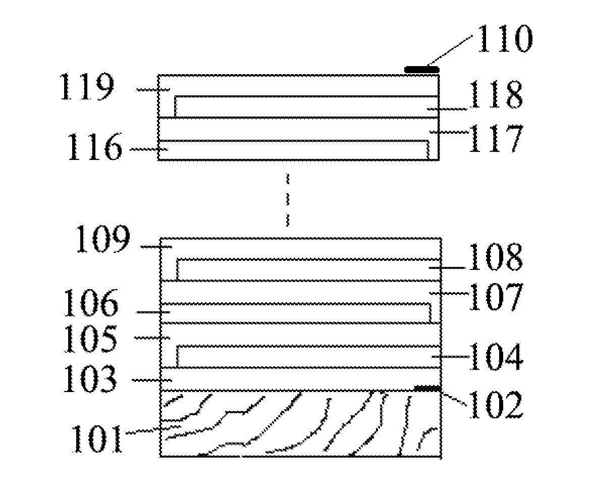
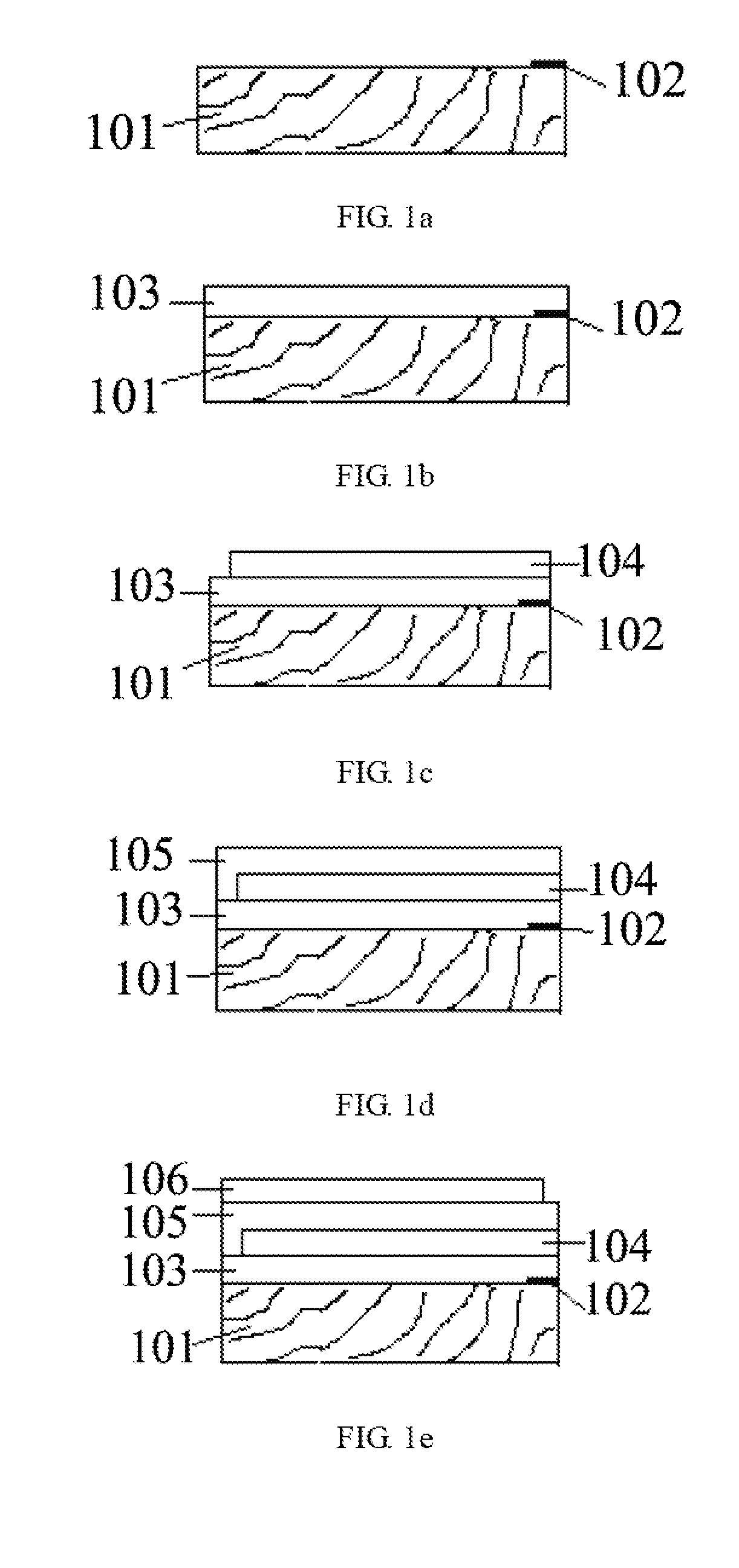
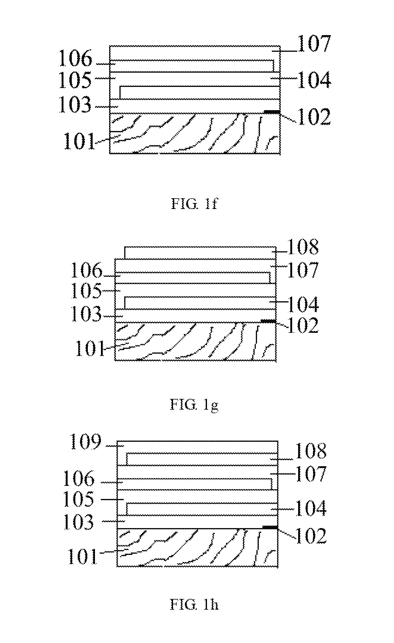
[0035]FIG. 1a-FIG. 1i are the schematic diagrams of the fabrication process of the first embodiment of the invention. FIG. 1i is the schematic diagrams of the end of the thin-film thermo-electric generator. In the first embodiment, the thin-film thermo-electric generator comprises an insulating substrate 101, an extractive electrode 102, a P-type thermo-electric thin-film layer 103, an insulating thin-film layer 104, a N-type thermo-electric thin-film layer 105, an insulating thin-film layer 106, a P-type thermo-electric thin-film layer 107, an insulating thin-film layer 108, a N-type thermo-electric thin-film layer 109, and an extractive electrode 110.

[0036]FIG. 1a shows a preset electrode 102 on a surface of the insulating substrate 101.

[0037]FIG. 1b shows a P-type thermo-electric thin-film layer 103 deposited on the side of the substrate on which the electrode is preset.

[0038]FIG. 1c shows an insulating thin-film layer 104 deposited on the P-type thereto-elect...

second embodiment

[0071]The thin-film thermo-electric generator can be made by using the insulating substrate as well as the substrate of P-type thermo-electric material (or metal) or N-type thereto-electric material (or metal). If the substrate of P-type thereto-electric material is applied, the cross-section diagram of the thin-film thereto-electric generator is shown in FIG. 2h. In this embodiment, the thin-film thereto-electric generator comprises a P-type thermo-electric material substrate 201, an insulating thin-film layer 202, a N-type thermo-electric thin-film layer 203, an insulating thin-film layer 204, a P-type thermo-electric thin-film layer 205, an insulating thin-film layer 206, a N-type thermo-electric thin-film layer 207, an extractive electrode 208 and an extractive electrode 209.

[0072]FIG. 2a shows the insulating thin-film layer 202 deposited on the P-type thermo-electric material substrate 201.

[0073]FIG. 2b shows the N-type thermo-electric thin-film layer 203 deposited on the insul...

third embodiment

The Third Embodiment

[0081]The embodiment of the present invention has some other variations. For example, based on the structure of thin-film thermo-electric generator applying P-type thereto-electric material as the substrate as shown in FIG. 2g, depositing multiple connections in series of three-layer PN junctions on the other side of the P-type thereto-electric substrate 201, an insulating thin-film layer is provided between every three-layer PN junction, to form a thin-film thereto-electric generator provided in the third embodiment. As shown in FIG. 3g, the thin-film thermo-electric generator in this embodiment comprises a substrate 301 of P-type thermo-electric material as the base of thin-film thermo-electric generator structure, an insulating thin-film layer 302, a N-type thermo-electric thin-film layer 303, an insulating thin-film layer 304, a P-type thermo-electric thin-film layer 305, an extractive electrode 208 and an extractive electrode 209.

[0082]FIG. 3a shows a substr...


PUM


Abstract

For the thin-film thermo-electric generator and fabrication method of this invention, a P-type thermo-electric thin-film layer, an insulating thin-film layer and a N-type thermo-electric thin-film layer is deposited on a substrate to form a three-layer PN junction, multiple three-layer PN junctions in series are available, an insulating thin-film layer is provided between every to serial three-layer PN junctions, and electrodes are extracted from the substrate and the outermost thin-film layer of the last three-layer thin-film PN junctions. The present invention applies the deposition of P-type thermo-electric thin-film layer, an insulating thin-film layer and a N-type thereto-electric thin-film layer to form a three-layer PN junction, thus a thermo-electric generator is formed, during the deposition of the insulating thin-film layer, intentionally sheltering the substrate and one end of the deposited thin-film layer and depositing the P-type or N-type materials on the substrate and one end of the deposited thin-film layer directly, to form a connection of PN junction or a serial connection between two PN junction, the separate connection of the P-type or N-type materials is not required, simplifying the fabrication processes of the thin-film thermo-electric generator, owning to the function of the thin-film thermo-electric materials and serial connection structure of multiple three-layer PN junctions, the performance of the thin-film thermo-electric generator is greatly improved.

Description

FIELD OF THE INVENTION[0001]This invention relates to thermo-electric technology, and more particularly to a thin-film thermo-electric generator and fabrication method thereof.BACKGROUND OF THE INVENTION[0002]The thermo-electric generator is a kind of generator made on the basis of Seebeck Effect, the heat energy is transformed into electric energy. The working principle of thermo-electric generator is that connecting one end of two different metals or two different types of thermo-electric conversion materials P-type and N-type semiconductors, placing this end in high temperature condition, and placing the other end in low temperature condition. Compared with the other end, the end in high temperature condition has better thermal activation and higher density of electrons and holes, the electrons and holes spread to the end in low temperature condition, thus an electric potential difference is formed in the end in low temperature condition. Combing a number of this kind of thermo-e...

Claims


Application Information

Patent Timeline
Patent Type & Authority Applications(United States)
IPC IPC(8): H01L35/32H01L21/20B82Y99/00H01L35/34
CPCH01L35/34H01L35/32H10N10/01H10N10/17
Inventor FAN, PINGZHANG, DONGPINGZJEMG, ZHUANGGHAOLIANG, GUANGXING
Owner SHENZHEN UNIV
Why Eureka
Try Eureka