Power Switch Ramp Rate Control Using Daisy-Chained Flops

a power switch and ramp rate technology, applied in the field of integrated circuits, can solve the problems of high total leakage current in the integrated circuit, static power consumption, and power gating, and achieve the effect of reducing the total leakage current of the integrated circuit, and improving the design of the integrated circui

Active Publication Date: 2011-08-18
APPLE INC
View PDF20 Cites 29 Cited by
  • Summary
  • Abstract
  • Description
  • Claims
  • Application Information

AI Technical Summary

Benefits of technology

[0008]In an embodiment, an integrated circuit may include one or more power managed blocks and a power manager circuit. The power manager circuit may be configured to generate a block enable for each power managed block and a block enable clock. The power managed block may generate local block enables to various power switches in the power managed block, staggering the block enables over two or more block enable clock cycles. In particular, the power managed block may include a

Problems solved by technology

Leakage currents in the idle transistors lead to static power consumption.
The faster transistors (those that react to input signal changes, e.g. on the gate terminals) also tend to have the higher leakage currents, which often results in high total leakage currents in the integrated circuit, especially in high performance devices.
Power gating presents challenges to the integrated circuit design.
As blocks are powered up a

Method used


Image

  • Power Switch Ramp Rate Control Using Daisy-Chained Flops
  • Power Switch Ramp Rate Control Using Daisy-Chained Flops
  • Power Switch Ramp Rate Control Using Daisy-Chained Flops

Examples


Embodiment Construction

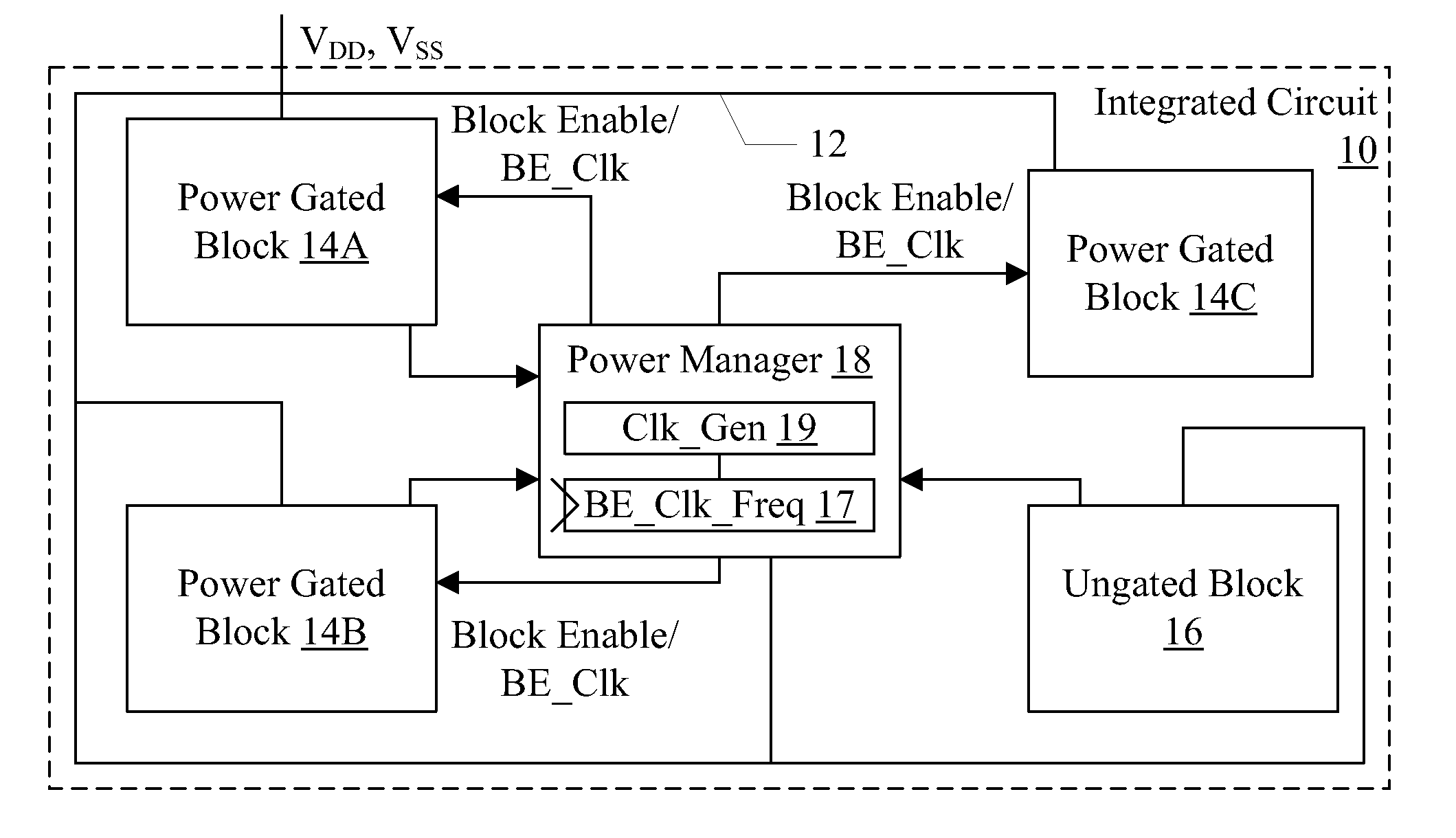
[0023]Turning now to FIG. 1, a block diagram of one embodiment of an integrated circuit 10 is shown. The integrated circuit 10 is coupled to receive power supply inputs (e.g. VDD and VSS, or power and ground, respectively). The VDD voltage may have a specified magnitude measured with respect to ground / VSS during use. More particularly, the VDD voltage may have a number of magnitudes that may be used for different operating points of the integrated circuit 10 during use. The integrated circuit 10 may include an interconnect, e.g. a global power supply grid, for each supply voltage, to distribute the voltage over an area occupied by the integrated circuit 10 (e.g. an area at the surface of a semiconductor substrate such as silicon). The global power supply grids are illustrated in FIG. 1 as the line 12 coupled to the blocks 14A-14C, 16, and 18 in FIG. 1. However, the grids may physically be arranged in a somewhat regular fashion, as described in more detail below.

[0024]The integrated ...


PUM


Abstract

In an embodiment, an integrated circuit may include one or more power managed blocks and a power manager circuit. The power manager circuit may be configured to generate a block enable for each power managed block and a block enable clock. The power managed block may generate local block enables to various power switches in the power managed block, staggering the block enables over two or more block enable clock cycles. In particular, the power managed block may include a set of series-connected flops that receive the block enable from the power manager circuit. The output of each flop may be coupled to a respective set of power switches and may enabled those switches. The change in current flow due to enabling and/or disabling the power managed block may thus be controlled. In an embodiment, the frequency of the block enable clock may be set to a defined value independent of process, voltage, and temperature conditions in the integrated circuit.

Description

BACKGROUND[0001]1. Field of the Invention[0002]This invention is related to the field of integrated circuits, and more particularly to supplying power to circuitry in integrated circuits.[0003]2. Description of the Related Art[0004]As the number of transistors included on an integrated circuit “chip” continues to increase, power management in the integrated circuits continues to increase in importance. Power management can be critical to integrated circuits that are included in mobile devices such as personal digital assistants (PDAs), cell phones, smart phones, laptop computers, net top computers, etc. These mobile devices often rely on battery power, and reducing power consumption in the integrated circuits can increase the life of the battery. Additionally, reducing power consumption can reduce the heat generated by the integrated circuit, which can reduce cooling requirements in the device that includes the integrated circuit (whether or not it is relying on battery power).[0005...

Claims


Application Information

Patent Timeline
IPC IPC(8): H01H35/00
CPCH03K19/0016
Inventor SUZUKI, SHINGOVON KAENEL, VINCENT R.TAKAYANAGI, TOSHINARIZIESLER, CONRAD H.MURRAY, DANIEL C.
Owner APPLE INC
Why Eureka
Try Eureka