
Fuel cell system and fuel cell state detection method

Inactive Publication Date: 2011-08-18
TOYOTA JIDOSHA KK
View PDF7 Cites 4 Cited by
  • Summary
  • Abstract
  • Description
  • Claims
  • Application Information

AI Technical Summary

Benefits of technology

[0008]The invention provides a fuel cell system and a fuel cell state detection method with which a cell where a malfunction has occurred or a malfunction is about to occur is detected easily.

Problems solved by technology

However, with the technology described in JP-A-2006-179338, it is difficult to distinguish normally operating cells and malfunctioning cells from each other.

Method used


Image

  • Fuel cell system and fuel cell state detection method
  • Fuel cell system and fuel cell state detection method
  • Fuel cell system and fuel cell state detection method

Examples


Embodiment Construction

[0030]An example embodiment of the invention will be described below.

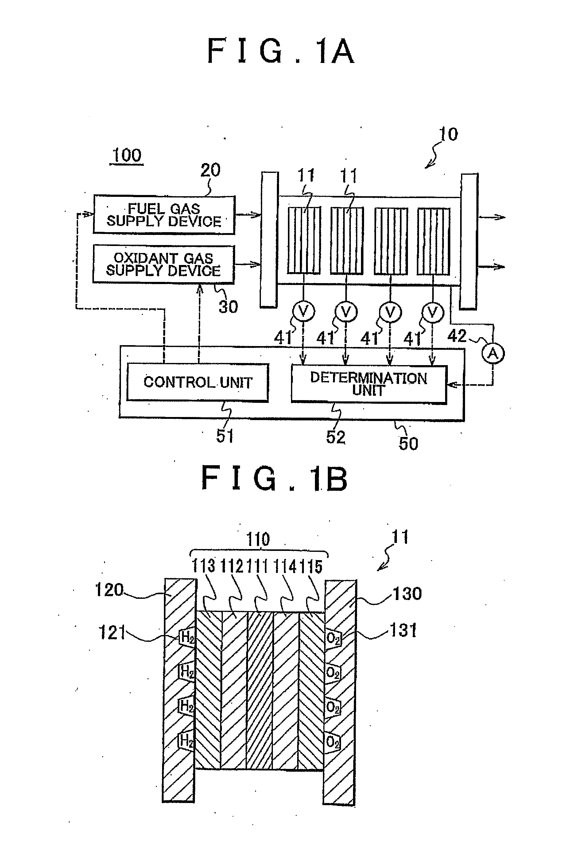
[0031]FIG. 1A and FIG. 1B are views illustrating a fuel cell system 100 according to an embodiment of the invention. FIG. 1A is a view schematically showing the overall configuration of the fuel cell system 100. FIG. 1B is a cross-sectional view schematically showing a cell 11, which will be described later in detail. As shown in FIG. 1A, the fuel cell system 100 includes a fuel cell stack 10, a fuel gas supply device 20, an oxidant gas supply device 30, voltage detection units 41, a current detection unit 42, a processing unit 50, etc.

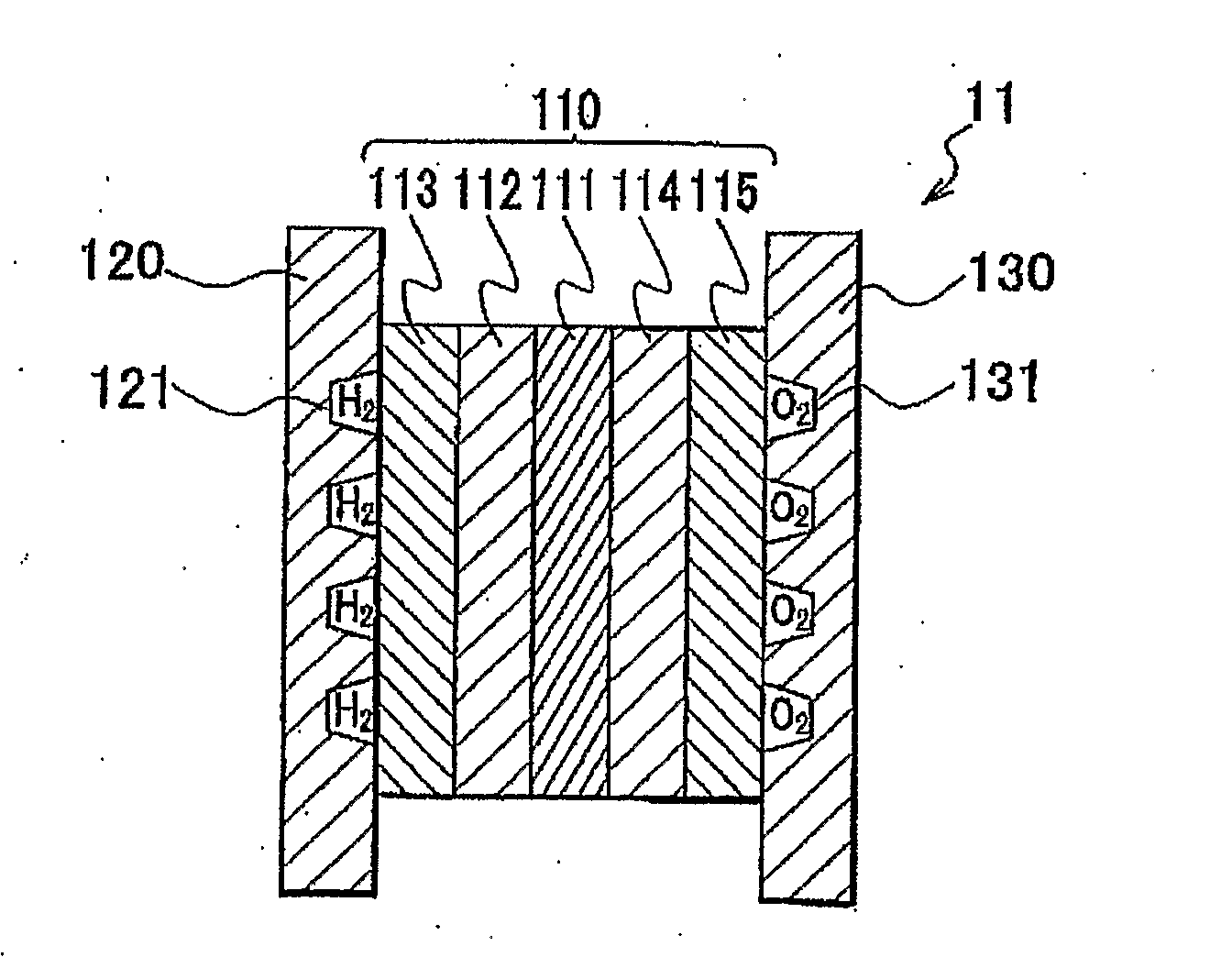
[0032]The fuel cell stack 10 includes at least one cell group that is formed of at least one cell 11. As shown in FIG. 1B, the cell 11 has a structure in which a membrane-electrode assembly (MEA) 110 is held between a separator 120 and a separator 130. In the MEA 110, an anode catalytic layer 112 and a gas diffusion layer 113 are arranged between an electrolyte membrane 111 and the s...


PUM


Abstract

A fuel cell system (100) includes: a fuel cell stack (10) formed by stacking a plurality of call groups each of which includes at least one cell (11); voltage detection units (41) that detect cell group voltages of the respective cell groups; and a determination unit (52) that determines whether the cell group voltage of a determination-target cell group that is selected from among the plurality of cell groups is equal to or lower than the threshold voltage that is obtained based on the average value and the standard deviation of the cell group voltages of the cell groups in a population that is formed of at least two of the cell groups selected from among the plurality of cell groups.

Description

BACKGROUND OF THE INVENTION[0001]1. Field of the Invention[0002]The invention relates to a fuel cell system and a fuel cell state detection method.[0003]2. Description of the Related Art[0004]Generally, fuel cells produce electric energy by using hydrogen and oxygen as fuel. Fuel cells have been widely developed as future energy supply systems because they are environmentally friendly and exhibit high energy efficiency. Especially, polymer electrolyte fuel cells have good startability because the temperature at which the polymer electrolyte fuel cells are actuated is lower than the temperatures at which various other fuel cells are actuated. Therefore, a lot of research has been made to place the polymer electrolyte fuel cells into practical use in various fields.[0005]A polymer electrolyte fuel cell has a structure in which a membrane electrode assembly (MEA) is held between separators. In the MEA, an anode is provided on one side of an electrolyte membrane, which is formed of a pr...

Claims


Application Information

Patent Timeline
IPC IPC(8): H01M8/04
CPCG01R31/3658H01M8/04552Y02E60/50H01M8/04679H01M8/249H01M8/04671G01R31/396
Inventor ARAKI, YASUSHI
Owner TOYOTA JIDOSHA KK
Features
  • Generate Ideas
  • Intellectual Property
  • Life Sciences
  • Materials
  • Tech Scout
  • Unparalleled Data Quality
  • Higher Quality Content
  • 60% Fewer Hallucinations
Learn More