

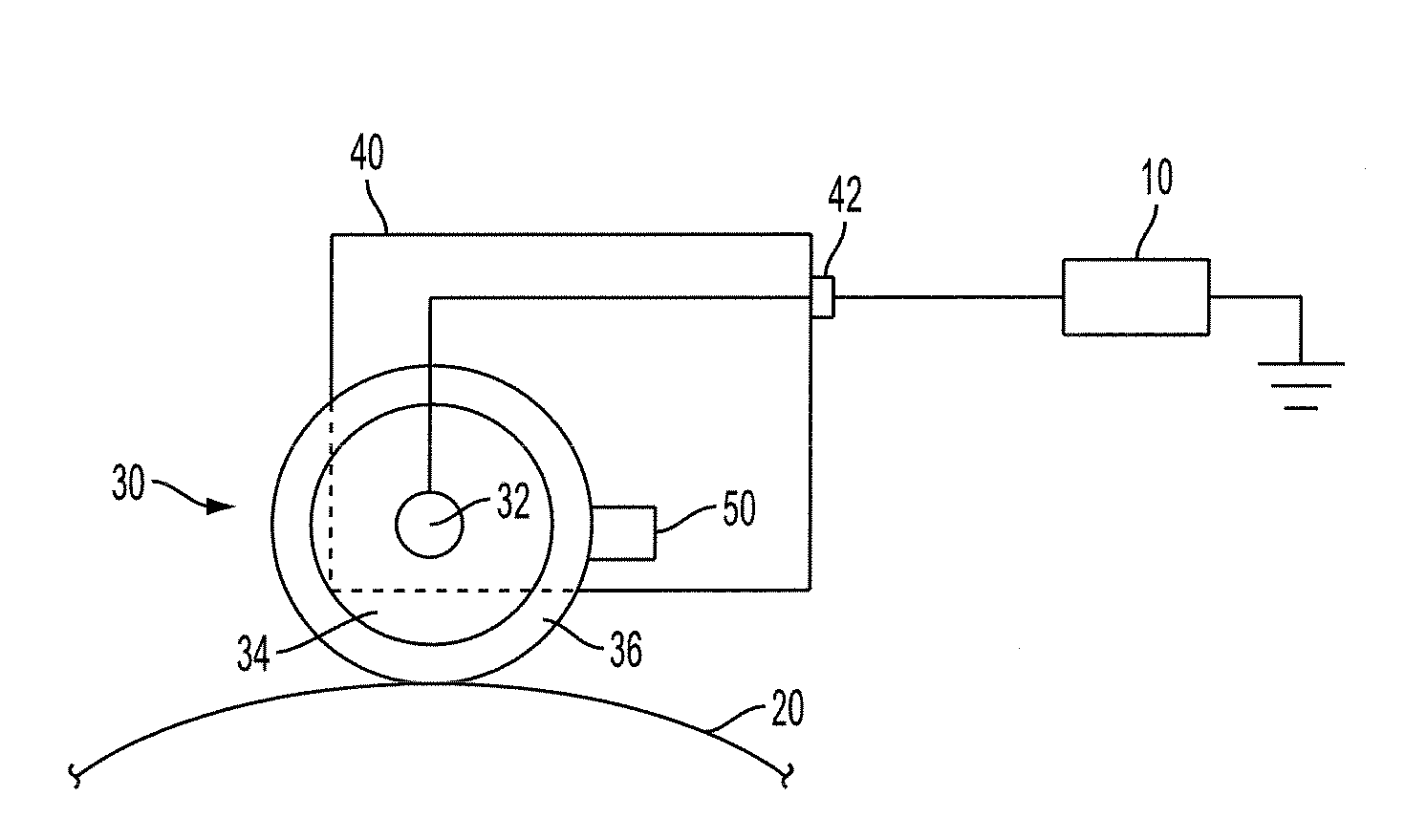
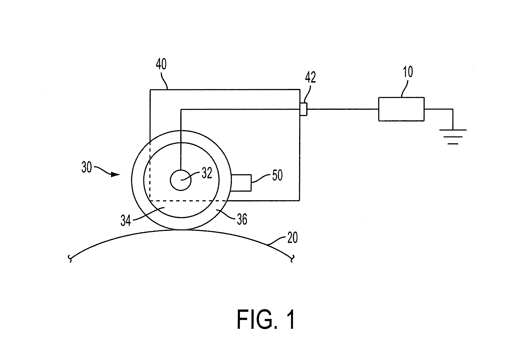
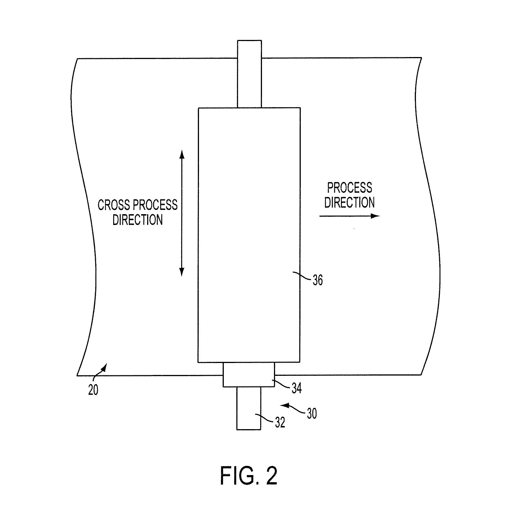
Bias charge roller comprising overcoat layer
a charge roller and overcoat technology, applied in the direction of coatings, instruments, corona discharge, etc., can solve the problems of inordinate maintenance of corotron wires, low charging efficiency, need for erase lamps and lamp shields, etc., and achieve the effect of reducing streaking and increasing service li
- Summary
- Abstract
- Description
- Claims
- Application Information
AI Technical Summary
Benefits of technology
Problems solved by technology
Method used
Image

Examples
example 1
[0060]A coating solution was prepared by mixing 65 wt % DORESCO® TA22-8 acrylic resin with 35 wt % CYMEL® 1170 glycoluril resin in methyl ethyl ketone solvent (˜17% total solids). 2% BYK-SILCLEAN® 3700 and 1% p-toluenesulfonic acid were added to the solution (percentages relative to the acrylic and glycoluril resins). A 4 μm overcoat layer was coated on a bias charge roller identical to the one used in Comparative Example 1 using a Tsukiage coater. The bias charge roller was then dried in a convection oven for 15 minutes at 140° C. to remove the solvent and cure the overcoat. The final composition of the overcoat layer was about 63 wt % acrylic resin, about 34 wt % glycoluril resin, about 2 wt % BYK-SILCLEAN® 3700, and about 1 wt % p-toluenesulfonic acid.
[0061]The bias charge roller was tested for charge uniformity prior to wear testing (t=0). The bias charge roller was then cycled 50,000 times in a Hodaka wear rate fixture, and subjected to charge uniformity testing using the same ...
PUM
 Abstract
Description
Claims
Application Information