Smart Injection Syring Systems Providing Real-Time User Feedback of Correct Needle Position

a syringe and real-time user technology, applied in the field of syringes, can solve the problems of limited knowledge and training of health care providers performing numerous injections, limited fluid flow, high resistance and very limited flow of operators, etc., to facilitate the proper site delivery

Inactive Publication Date: 2011-08-18
EAST CAROLINA UNIVERISTY
View PDF3 Cites 67 Cited by
  • Summary
  • Abstract
  • Description
  • Claims
  • Application Information

AI Technical Summary

Benefits of technology

[0006]Embodiments of the present invention are directed to syringes that can provide visual or audio location feedback to

Problems solved by technology

Unfortunately, some health care providers perform numerous injections with limited knowledge and training in surface anatomy, tissue planes, and musculoskeletal compartments.
For example, if the tip of the injecting needle is buried in the substance of a tendon, the operator

Method used


Image

  • Smart Injection Syring Systems Providing Real-Time User Feedback of Correct Needle Position
  • Smart Injection Syring Systems Providing Real-Time User Feedback of Correct Needle Position
  • Smart Injection Syring Systems Providing Real-Time User Feedback of Correct Needle Position

Examples


example 1

[0049]As illustrated in FIGS. 4-6, a syringe system 100 includes a syringe 115 with a syringe plunger 115a in a syringe body 115b, which is in communication with a needle 125. Two support members or housings 120a, 120b are configured to connect sensors 130a, 130b to the syringe 115. The sensor 130a is a force sensor configured to detect an amount of force with which the user depresses the plunger 115a. As illustrated in FIG. 4, the sensor 130a is connected to the plunger 115a by the housing 120b. The sensor 130b is a displacement sensor that is in communication with the plunger 115a and detects the displacement of the plunger 115a as the user depresses the plunger 115a.

[0050]In operation, the force sensor 130a detects the force that the user applies to the plunger 115a, and the displacement sensor 130b detects the displacement of the plunger 115a as the plunger 115a is depressed. Accordingly, the sensors 130a, 130b are positioned on the outside components of the syringe 115 such th...

example 2

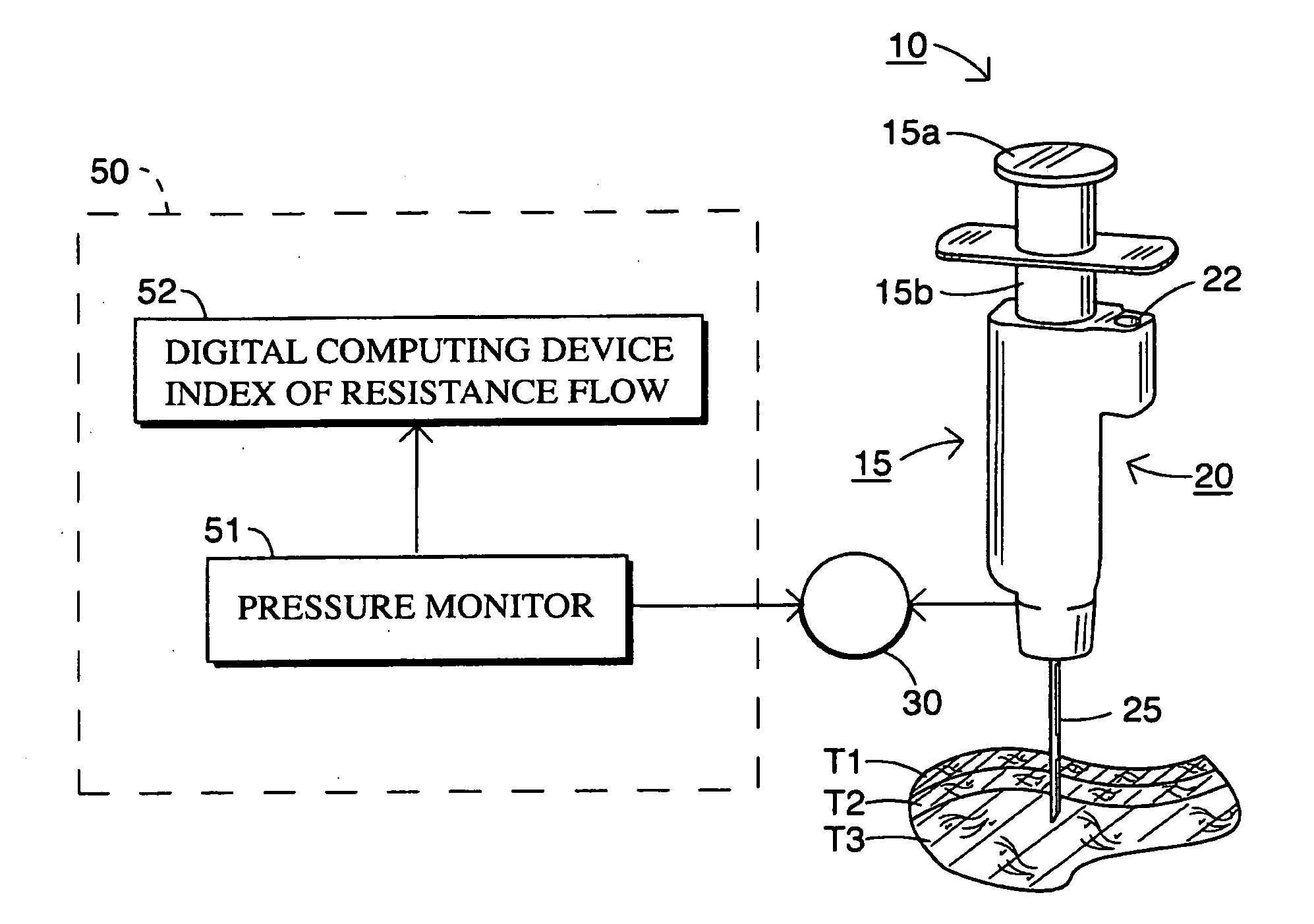
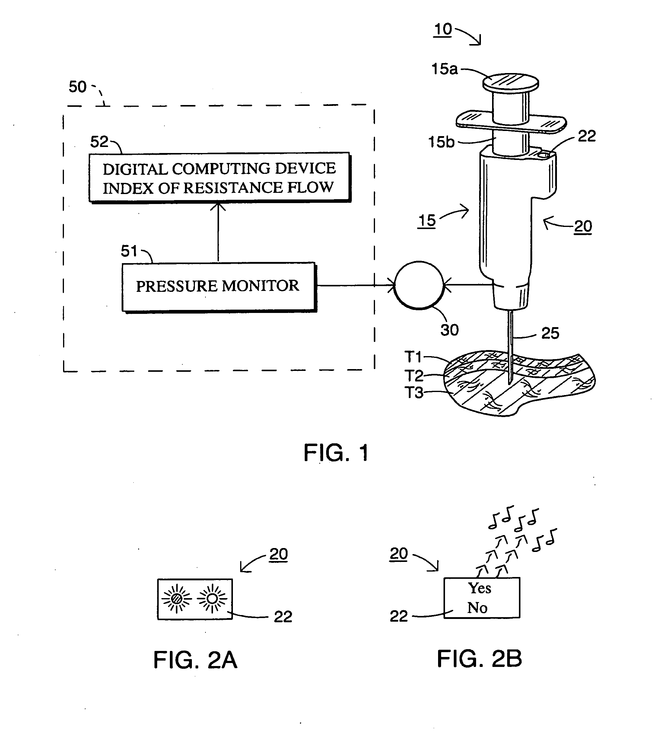
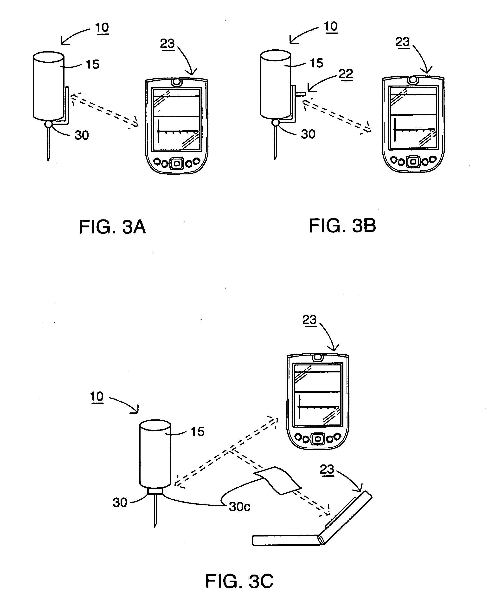
[0056]With reference to FIGS. 1-3, in particular exemplary embodiments, the sensors 30 are a pressure transducer and / or flow sensor that comes into physical contact with the fluid in the syringe body 15b. For example, a pressure and / or flow sensor can be provided in the housing 20 between the needle 25 and the syringe body 15b such that the housing provides a fluid channel that can be generally the same diameter as the fluid channel adjacent the needle such that alteration of the syringe 15 is reduced. Fluid impedance can be tested by a user by inserting the needle 25 into the tissue T1, T2 and T3 and then injecting a relatively small amount of fluid into the tissue T1, T2 and T3. The pressure and flow readings from the sensors 30 can then be converted into impedance, e.g., by the computer device 23 and relayed to the user via the user feedback indicator member 22.

example 3

[0057]With continued reference to FIGS. 1-3, the sensor(s) 30 are force and / or pressure sensors that measure the impedance or force / pressure on the needle 25 during insertion into the tissue T1, T2, T3. For example, the sensor(s) 30 can be piezoelectric or other suitable force sensors positioned on the needle to detect force as a function of time during needle insertion. In particular embodiments, the force and / or pressure sensor(s) 30 can be in communication with the needle 25 and / or the sensor(s) can detect a deforming force on the needle 25. The force applied to the needle 25 (or on the syringe 15) can be measured while the needle 25 is inserted into the tissue T1, T2, T3. Generally continuous force readings may be taken, and a force curve may be created. For example, the user may apply constant force during insertion, and then the force may drop when the needle 25 reaches the joint cavity tissue T3. The computer device 23 may be configured to detect the reduction in force when t...


PUM


Abstract

Syringe assemblies include a syringe with a syringe body (15b) defining a fluid cavity in fluid communication with an injection needle (25); a force, pressure and/or flow sensor (30) in fluid communication with the needle; and a user feedback unit (22) in electrical communication with the sensor and configured to provide user feedback based on data from the force, pressure and/or flow sensor.

Description

RELATED APPLICATIONS[0001]This application claims priority to U.S. Provisional Patent Application No. 60 / 956,235, filed Aug. 16, 2007, the disclosure of which is hereby incorporated by reference in its entirety.FIELD OF THE INVENTION[0002]The invention relates to syringes and may be particularly suitable for syringes that inject medicaments into joint spaces.BACKGROUND OF THE INVENTION[0003]It is routine in the course of treating musculoskeletal complaints, injuries, and disease to utilize injections of several types for the relief of pain and inflammation or to promote cartilage repair. Injection types include steroid injection, local anesthetics, hyaluronic acid, or mixtures of the above. One aspect of performing this injection is the proper location of the injected fluid. Unfortunately, some health care providers perform numerous injections with limited knowledge and training in surface anatomy, tissue planes, and musculoskeletal compartments. This knowledge can be the difference...

Claims


Application Information

Patent Timeline
IPC IPC(8): A61M5/31G09B23/28A61M5/315
CPCA61B5/1422A61B17/3401A61B2019/464A61M5/31511A61M5/32A61M5/3287A61M2205/58A61M5/486A61M2205/33A61M2205/332A61M2205/3569A61M2205/3592A61M2205/50A61M5/427A61B2090/064
Inventor BARTLETT, EDWIN C.
Owner EAST CAROLINA UNIVERISTY
Why Eureka
Try Eureka