Device for measuring torsions, bendings, and the like, and corresponding manufacturing method

a technology of torsions and bendings, applied in the direction of manufacturing tools, material strength using steady bending forces, instruments, etc., can solve the problems of extremely sensitive devices and decrease in dimensions, and achieve the effects of increasing the sensitivity to load, increasing the accuracy of measuring devices, and increasing the reliability of fixed connections

Inactive Publication Date: 2011-08-25
ROBERT BOSCH GMBH
View PDF11 Cites 13 Cited by
  • Summary
  • Abstract
  • Description
  • Claims
  • Application Information

AI Technical Summary

Benefits of technology

[0013]According to one preferred refinement, the device, in particular the metal plate, includes a recess. The advantage is that the device may be optimally adapted to specific requirements of the component, or also measuring requirements, by an appropriate design of the shape of the recess. In addition, the reliability of the fixed connection between the device, in particular the metal plate, and the component, as well as the measuring accuracy of the device are increased. Adapting the shape of the recess allows the load on the device, more precisely, on the gauges, to be influenced, depending on the requirements. If no recess is present, the load is distributed over the entire device. In particular for a metal plate having a recess in the region of the gauges, the sensitivity to the load is increased due to the fact that the load is concentrated in the region of the recess.
[0014]According to one preferred refinement, the device includes a housing. The advantage is that the gauge system may thus be protected from damage. Additional calibrations of the device are unnecessary. Within the meaning of the present invention, the term “housing” generally refers to any system used to protect the device from damage. The term “housing” is therefore also understood in particular to mean non-aging passivation, for example a nitride layer.
[0015]According to one preferred refinement, the device may be fixed in a recess of the component. This results in the advantage that measurements of torsions, bendings, or the like, of the component may also be carried out in regions of the component which would not be accessible without the recess.
[0016]According to one preferred refinement, the device, in particular the evaluation device, includes a transmitter for wireless transmission of data. The advantage is that for rotating components, for example, complicated laying of connecting cables may be dispensed with, thus expanding the overall field of application of the device and at the same time reducing the complexity for using the device. In particular when the evaluation device includes the transmitter, additional connections between the transmitter and the evaluation device may be dispensed with, which greatly simplifies the manufacture of the device.
[0017]According to one preferred refinement, the insulating layer includes an oxide layer. The advantage is that the insulating layer may be applied using industrial-scale processes, in particular PECVD.
[0018]According to one preferred refinement of the method according to the present invention, the device is fixed to the component by welding. The advantage is that a reliable and resistant fixed connection between the device and the component is made possible.

Problems solved by technology

Lastly, the device is extremely sensitive and allows a decrease in the dimensions and therefore in the space requirements at the position to be measured on the component.

Method used


Image

  • Device for measuring torsions, bendings, and the like, and corresponding manufacturing method
  • Device for measuring torsions, bendings, and the like, and corresponding manufacturing method
  • Device for measuring torsions, bendings, and the like, and corresponding manufacturing method

Examples


Embodiment Construction

[0028]In the figures, identical or functionally equivalent elements are denoted by the same reference numerals.

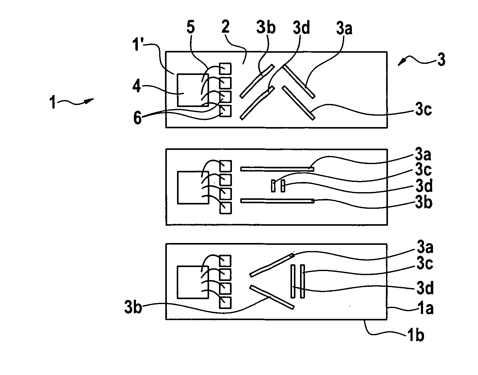
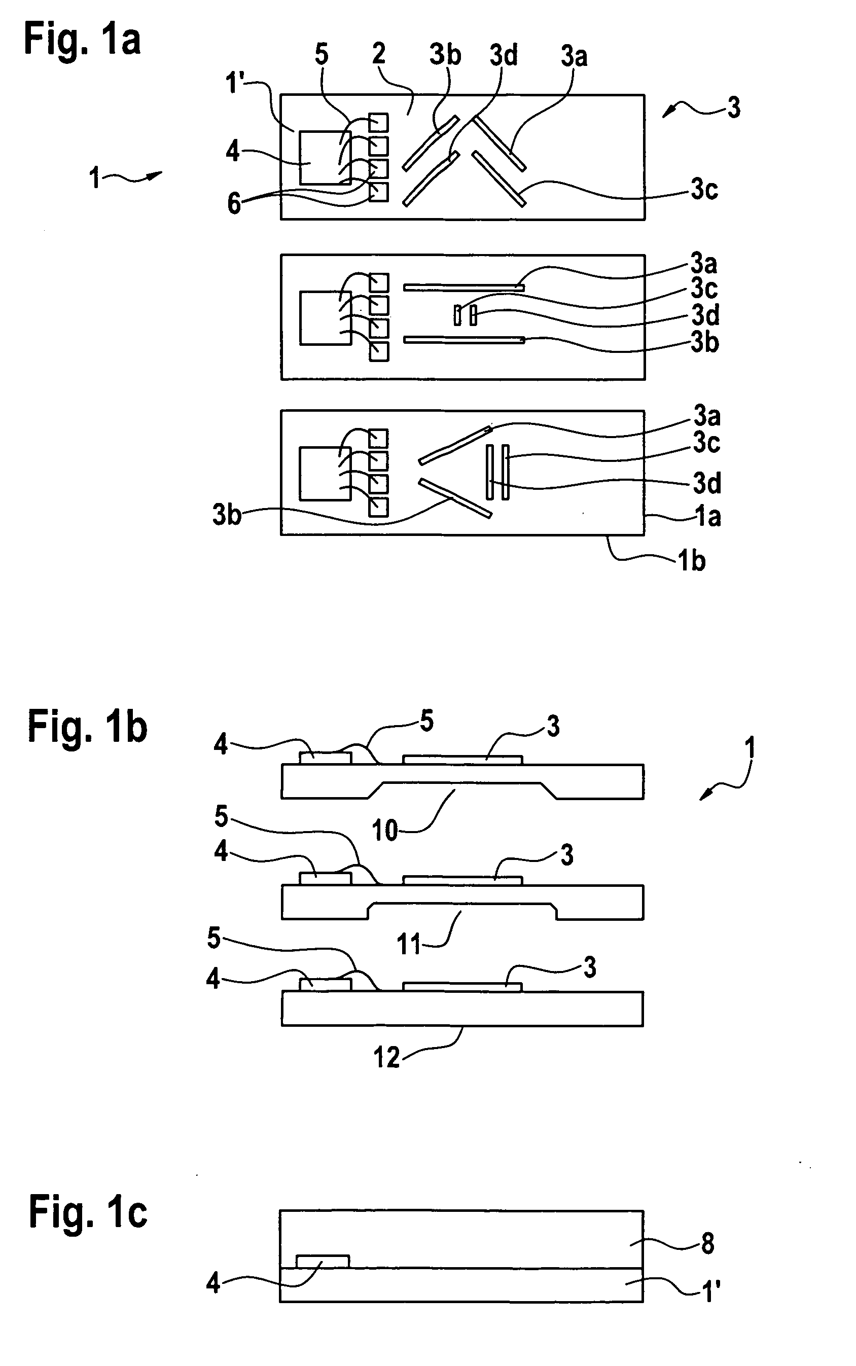
[0029]FIG. 1 shows a device according to one first specific embodiment of the present invention, in a top view.

[0030]In FIG. 1, reference numeral 1 denotes a device for measuring torsions, bendings, and the like, of a component (not shown) according to the first specific embodiment of the present invention. Device 1 includes a polished steel plate 1′ as the substrate, to which an insulating layer 2 is applied. A sensing layer 3 which has been partially removed by etching is in turn applied to insulating layer 2. The regions of sensing layer 3 which are not removed form a gauge system 3a, 3b, 3c, 3d having gauges 3a, 3b, 3c, 3d; gauges 3a, 3c and 3b, 3d in each case are oriented parallel to one another. In addition, gauges 3b, 3d are oriented mirror symmetrically with respect to gauges 3a, 3c, so that in each case the gauges are essentially oriented in a V shape.

[0031]Accord...


PUM

PropertyMeasurementUnit
metallicaaaaaaaaaa
insulatingaaaaaaaaaa
piezoelectricaaaaaaaaaa

Abstract

A device for measuring torsions, bendings, and the like, of a target component includes a metallic substrate, an insulating layer, and a sensing layer in the form of a gauge system. The device is configured to be fixed to the target component via a fixed connection.

Description

BACKGROUND OF THE INVENTION[0001]1. Field of the Invention[0002]The present invention relates to a device for measuring torsions, bendings, and the like, and a corresponding manufacturing method.[0003]2. Description of Related Art[0004]It is known to use strain gauges for measuring torsions or bendings of components. Strain gauges are known from, e.g., published German utility model application document DE 90 170 56 U1, for example, and generally include a measuring grid foil made of resistance wire having a thickness of a few μm. The measuring grid foil is laminated onto a thin plastic substrate, in particular a film, etched out, and provided with electrical connections. Polyamide or epoxy resin is generally used as the carrier film. The strain gauge is then glued to a measuring site of a component to be measured.[0005]As a result of the gluing, the strain gauge has a limited resolution accuracy due to the fact that the adhesive bond itself is part of the elongation, so that the el...

Claims


Application Information

Patent Timeline
Patent Type & Authority Applications(United States)
IPC IPC(8): G01N3/22B05D3/06B23K31/02G01N3/20
CPCG01B7/16G01L3/108G01L1/2287
Inventor HUELS, JANHENNING, FRANKFREY, WILHELM
Owner ROBERT BOSCH GMBH
Why Eureka
Try Eureka