Engine starter control apparatus

a control apparatus and engine technology, applied in the direction of engine starters, machines/engines, electric motor starters, etc., can solve the problems of increasing the required period of time, increasing the concern for the mechanical wear of the pinion, and increasing the time required to complete the rotation. , to achieve the effect of minimizing the length of time the pinion undergoes, increasing the tim

Inactive Publication Date: 2011-08-25
DENSO CORP
View PDF8 Cites 16 Cited by
  • Summary
  • Abstract
  • Description
  • Claims
  • Application Information

AI Technical Summary

Benefits of technology

[0008]It is therefore an object to provide an improved structure of a starter control apparatus designed to minimize the wear of parts of a starter.
[0011]When the pinion is being rotated by the ring gear (e.g., the speed of the ring gear is higher than that of the motor), the magnitude of torque exerted by the ring gear on the pinion when the motor is in the on-state to produce torque is thought of as being smaller than that when the motor is in the off-state. This means that the mechanical wear of the pinion arising from being rotated by the ring gear will be small when the motor is running to exert the torque on the pinion. The starter control apparatus, as described above, keeps the motor rotating when the pinion is in engagement with the ring gear, thus resulting in a decrease in torque exerted by the ring gear on the pinion to minimize the wear of the pinion.
[0013]In view of the above facts, the starter control apparatus works to determine the time when the rotation of the pinion is to be stopped based on the period of time consumed between when the engagement release means instructs the starter to release the engagement of the pinion with the ring gear and when the release of the engagement of the pinion with the ring gear is completed actually, thus keeping the pinion rotated by the motor for as long as possible when the pinion is in engagement with the ring gear, which minimizes the wear of the pinion. The motor is stopped at an optimum time selected based on the required period of time, thus enabling the length of time the motor is to be kept rotated to be minimized.
[0014]The starter control apparatus further comprises release completion determining means for determining whether the release of the engagement of the pinion with the ring gear has been completed or not after the engagement release means instructs the starter to release the engagement of the pinion with the ring gear and pinion rotation stop determining means for determining the time when the rotation of the pinion is to be stopped based a result of the determination of whether the release of the engagement of the pinion with the ring gear has been completed or not. This structure is operable to stop the rotation of the pinion through the motor after completion of the release of engagement of the pinion with the ring gear, thus minimizing the length of time the motor is to be kept rotated.
[0018]If the engine has failed to continue to run by itself due to a misfire of an air-fuel mixture after the disengagement of the pinion from the ring gear, but before the engine is fired up and starts to be run only by combustion of the mixture, the starter control apparatus is operable to bring the pinion into engagement with the ring gear to crank the engine again. In view of this fact, the starter control apparatus may be designed to have engine-fired up determining means for determining whether the engine has been fired up and started to run by itself or not after the engine starts to be cranked and pinion stop inhibiting means for inhibiting rotation of the pinion from being stopped until the engine-fired up determining means determines that the engine has been fired up and started to run by itself. This causes the pinion to be kept rotated for a period of time between the pinion is disengaged from the ring gear and when the engine is fired up, thereby enabling the engine to be restarted quickly.
[0020]The starter control apparatus may further comprise pinion stopping time determining means for determining a pinion stopping time that is the time when the motor is to be turned off to stop the rotation of the pinion. The engagement release means may release the engagement of the pinion with the ring gear before the pinion stopping time is reached. In the case where the starter is so designed that the pinion is disengaged from the ring gear after the motor is turned off to stop the rotation of the pinion, the pinion will be kept in engagement with the ring gear after the rotation of the pinion is stopped, thus resulting in an increased length of time the pinion is subjected to the rotation of the ring gear, which leads to a greater concern about the wear of rotating parts of the starter such as the pinion and a shaft of the pinion. The starter control apparatus, as described above, works to complete the disengagement of the pinion from the ring gear before the motor is stopped, thereby minimizing the length of time the pinion undergoes the rotation of the ring gear, that is, the wear of the rotating parts of the starter.

Problems solved by technology

This leads to a greater concern about the mechanical wear of the pinion.
This means that the mechanical wear of the pinion arising from being rotated by the ring gear will be small when the motor is running to exert the torque on the pinion.
For instance, grease escapes from sliding parts of the starter or parts of the starter are worn away with the aging of the starter, which will result in an increase in the required period of time.
Moreover, the lower the temperature of the starter, the higher the viscosity of the grease applied to the sliding parts of the starter, which results in an increase in the above release-required time.
This causes the electromotive force to be induced in the first solenoid when switched from the on-state to the off-state to release the engagement of the pinion with the ring gear to be greater than that induced in the second solenoid when switched from the on-state to the off-state to stop the motor, thus resulting in an increase in lag in pulling the pinion to disengage the pinion from the ring gear.
In the case where the starter is so designed that the pinion is disengaged from the ring gear after the motor is turned off to stop the rotation of the pinion, the pinion will be kept in engagement with the ring gear after the rotation of the pinion is stopped, thus resulting in an increased length of time the pinion is subjected to the rotation of the ring gear, which leads to a greater concern about the wear of rotating parts of the starter such as the pinion and a shaft of the pinion.

Method used


Image

  • Engine starter control apparatus
  • Engine starter control apparatus
  • Engine starter control apparatus

Examples


Embodiment Construction

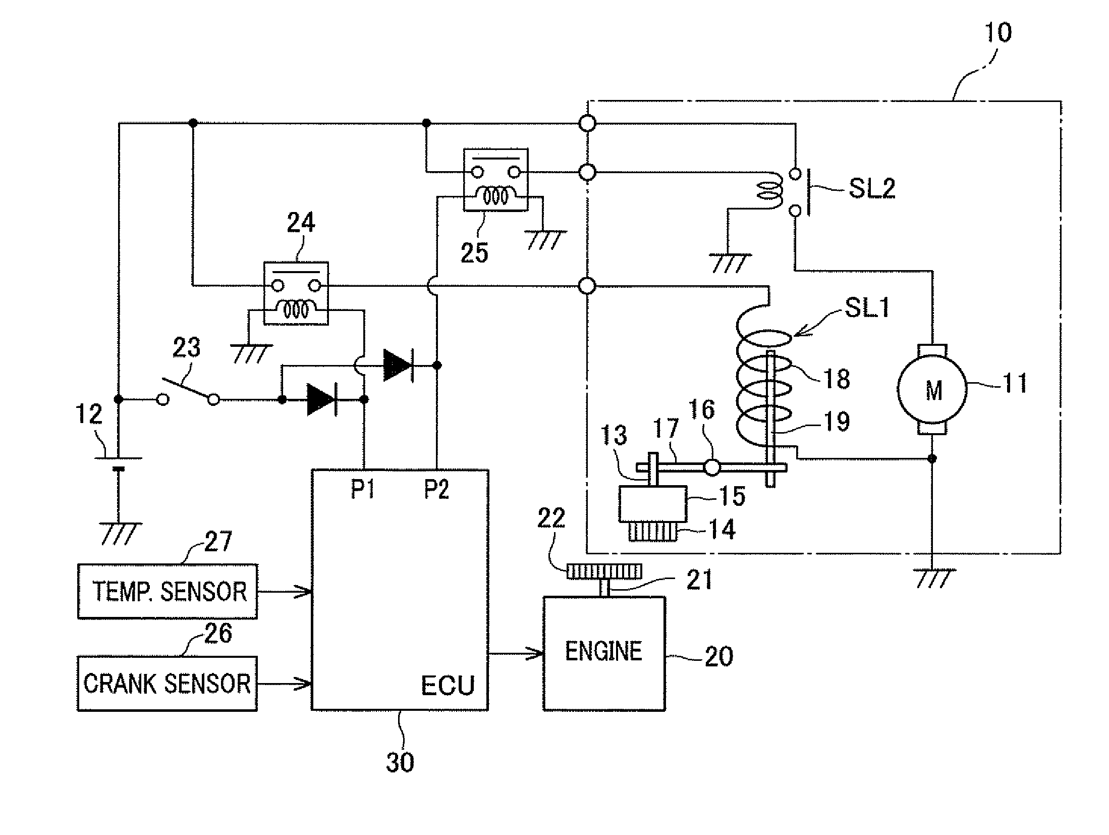
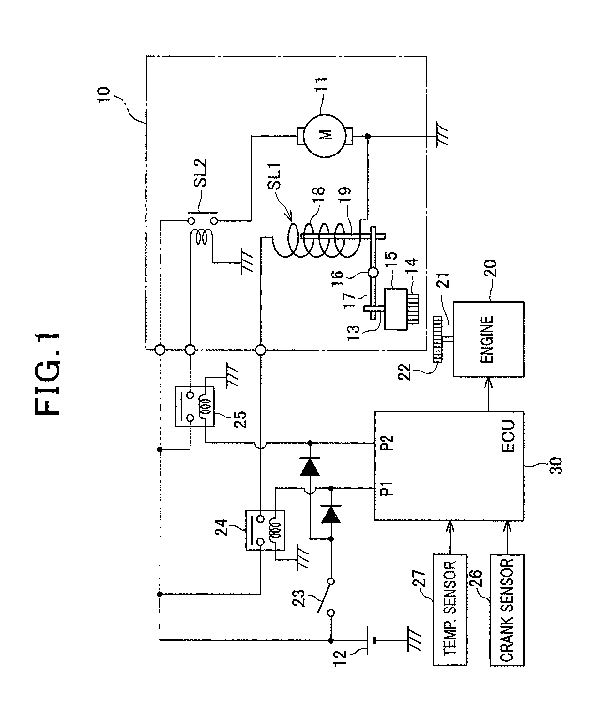
[0032]Referring to the drawings, wherein like reference numbers refer to like parts in several views, particularly to FIG. 1, there is shown an engine starter controller which will be described as being embodied as an automatic engine stop / restart system designed to control stop and restart of an internal combustion engine 20 mounted in a motor vehicle automatically. The engine stop / restart system is equipped with an electronic control unit (ECU) 30 and works to control the quantity of fuel to be injected into the engine 20, the ignition timing of the fuel in the engine 20, and a stop / restart operation of the engine 20.

[0033]When it is required to start, stop, or restart the engine, the engine stop / restart system controls an operation of a starter 10. The starter 10 is equipped with an electric motor 11 which is to be rotated upon supply of electric power from a storage battery 12 installed in the vehicle. The electric motor 11 has an output shaft (not shown) on which a pinion shaft...


PUM


Abstract

A starter control apparatus is provided which is used with a starter equipped with a pinion engageable with a ring gear coupled to an output shaft of an engine and a motor operable to rotate the pinion to crank the engine. The starter control apparatus works to determine whether the engine has been placed to continue to run by itself after cranked by the motor or not. When such a condition is encountered, the starter control apparatus releases the engagement of the pinion with the ring gear while keeping the pinion rotated by the motor, thereby decreasing the torque exerted by the ring gear on the pinion to minimize the wear of the pinion.

Description

CROSS REFERENCE TO RELATED DOCUMENT[0001]The present application claims the benefits of Japanese Patent Application No. 2010-34313 filed on Feb. 19, 2010, the disclosure of which is incorporated herein by reference.BACKGROUND[0002]1. Technical Field[0003]The present invention relates generally to a controller for an engine starter which may be employed in automotive vehicles, and more particularly to such a controller designed to release engagement of a pinion of the starter with a ring gear of an engine after completion of cranking of the engine.[0004]2. Background Art[0005]In typical automotive vehicles, starting of an engine after being stopped is achieved by applying initial torque to an output shaft (i.e., a crankshaft) of the engine using a starter. Specifically, a starter controller energizes the starter to thrust a pinion in an axial direction thereof and bring it into engagement with a ring gear coupled mechanically to the crankshaft of the engine. The starter controller th...

Claims


Application Information

Patent Timeline
Patent Type & Authority Applications(United States)
IPC IPC(8): F02N15/00
CPCF02N11/0848F02N15/02Y10T74/131Y10T74/132F02N2200/022F02N11/0851
Inventor NOTANI, HIDEYA
Owner DENSO CORP
Why Eureka
Try Eureka