Method of and Printable Compositions for Manufacturing a Multilayer Carbon Nanotube Capacitor

a carbon nanotube and capacitor technology, applied in the field of energy storage technology, can solve the problems of difficult manufacturing and scaling up to commercial quantities, the alignment method based on the growth of cnts is not practical beyond the laboratory environment, and the faradaic battery and conventional dielectric capacitors have drawbacks, etc., to achieve the effect of increasing the specific power (or power density), reducing the cost of manufacturing, and increasing the specific energy

Inactive Publication Date: 2011-08-25
NTHDEGREE TECH WORLDWIDE
View PDF14 Cites 72 Cited by
  • Summary
  • Abstract
  • Description
  • Claims
  • Application Information

AI Technical Summary

Benefits of technology

The exemplary capacitor embodiments have a structure different from the structures of prior art capacitors, a different fabrication method, and different compositions of matter. Various exemplary capacitor embodiments have an additional layer, namely, free CNTs which are translationally and/or rotationally moveable in an ionic liquid 140. Many of the exemplary capacitor embodiments have a secondary support structure for the fixed CNTs, which provides a second support to the fixed CNTs at a second location which is separate and spaced apart from a first support location, such as the substrate. The fixed CNTs and the free CNTs are uncapped at least at one end, and have an interior diameter matched to be slightly greater than the ion size of a selected ionic liquid. The fixed CNTs have not been grown on an electrode or transferred directly from a growth plate, but have been dispersed in an ionic liquid and deposited with an i...

Problems solved by technology

Other available energy storage technologies such as the Faradaic battery and conventional dielectric capacitors have drawbacks.
Other attempts to use carbon nanotubes have included use of aligned CNTs having either a closed (capped) or an open (or uncapped) end, but have proved extraordinarily difficult to manufacture and scale up to commercial quantities.
While theoretically feasible, such alignment methods based on the growth of the CNTs are not practical beyond a laborato...

Method used


Image

  • Method of and Printable Compositions for Manufacturing a Multilayer Carbon Nanotube Capacitor
  • Method of and Printable Compositions for Manufacturing a Multilayer Carbon Nanotube Capacitor
  • Method of and Printable Compositions for Manufacturing a Multilayer Carbon Nanotube Capacitor

Examples


Embodiment Construction

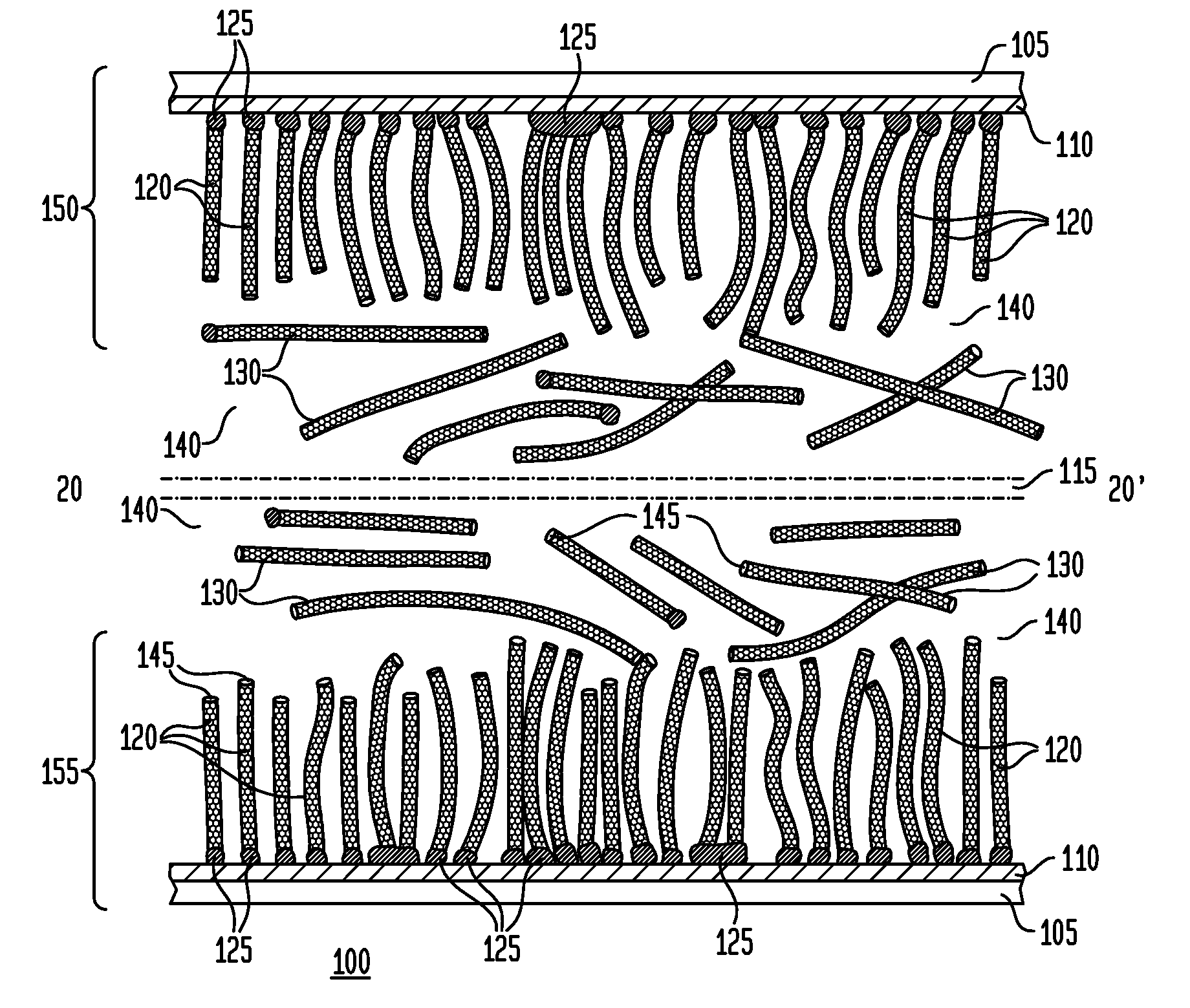
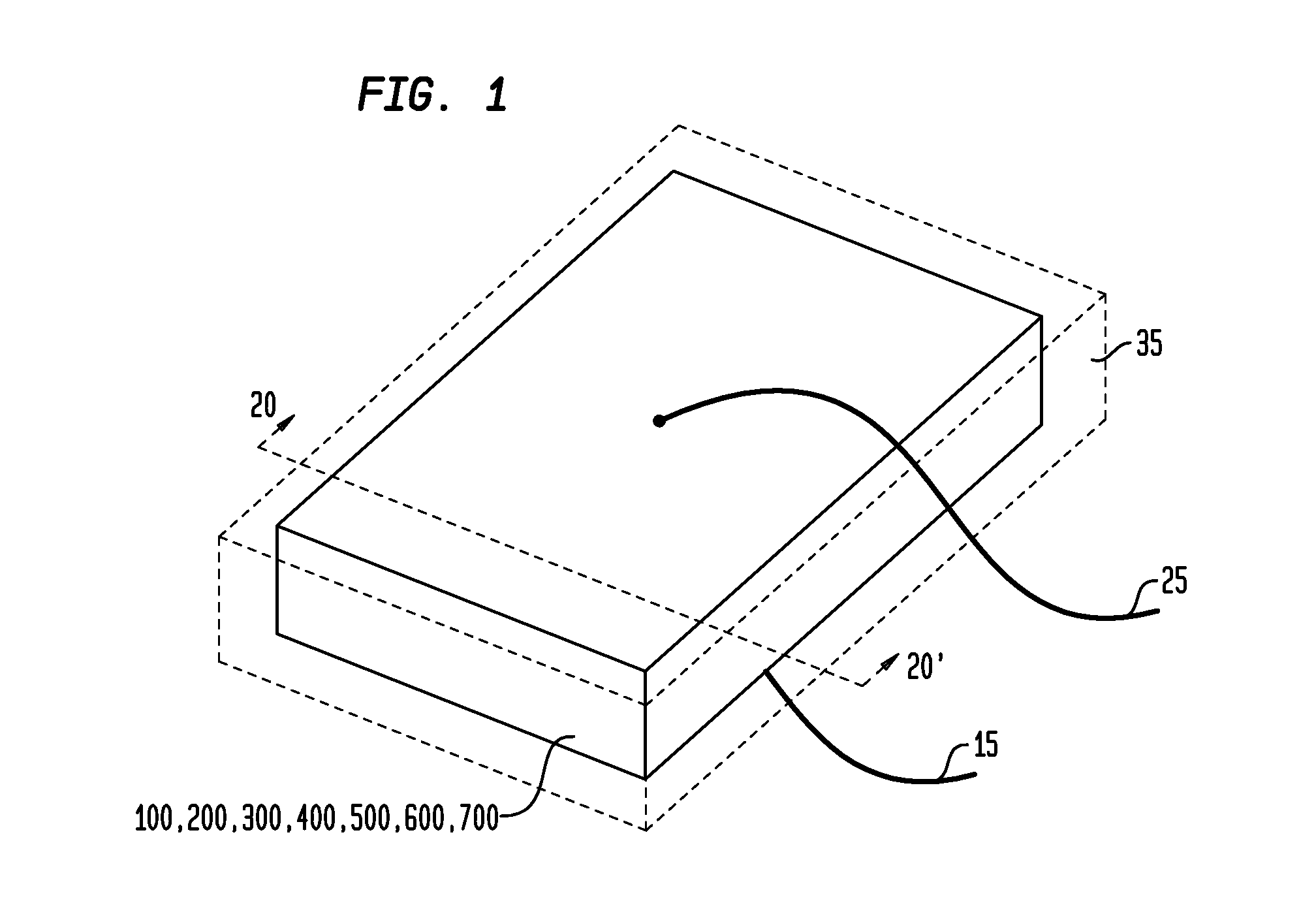
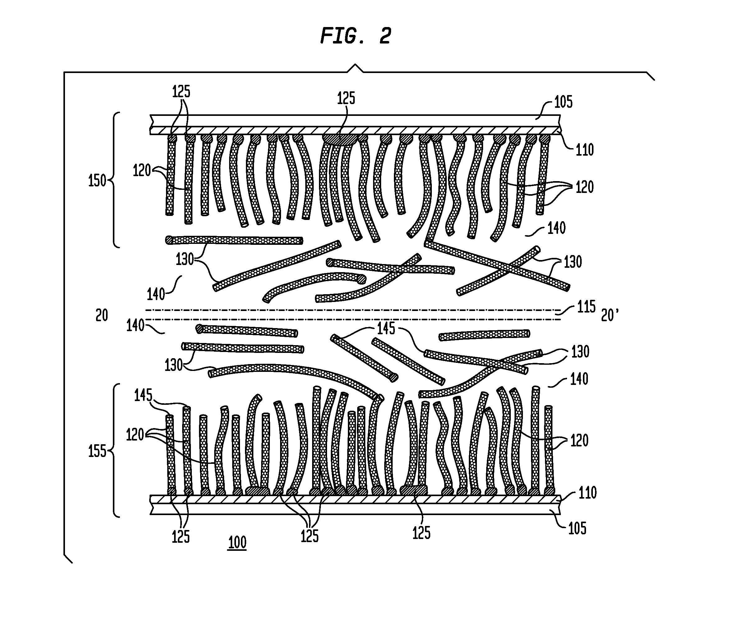
While the present invention is susceptible of embodiment in many different forms, there are shown in the drawings and will be described herein in detail specific exemplary embodiments thereof, with the understanding that the present disclosure is to be considered as an exemplification of the principles of the invention and is not intended to limit the invention to the specific embodiments illustrated. In this respect, before explaining at least one embodiment consistent with the present invention in detail, it is to be understood that the invention is not limited in its application to the details of construction and to the arrangements of components set forth above and below, illustrated in the drawings, or as described in the examples. Methods and apparatuses consistent with the present invention are capable of other embodiments and of being practiced and carried out in various ways. Also, it is to be understood that the phraseology and terminology employed herein, as well as the a...


PUM

PropertyMeasurementUnit
Diameteraaaaaaaaaa
Diameteraaaaaaaaaa
Diameteraaaaaaaaaa

Abstract

Multilayer carbon nanotube capacitors, and methods and printable compositions for manufacturing multilayer carbon nanotubes (CNTs) are disclosed. A first capacitor embodiment comprises: a first conductor; a plurality of fixed CNTs in an ionic liquid, each fixed CNT comprising a magnetic catalyst nanoparticle coupled to a carbon nanotube and further coupled to the first conductor; and a first plurality of free CNTs dispersed and moveable in the ionic liquid. Another capacitor embodiment comprises: a first conductor; a conductive nanomesh coupled to the first conductor; a first plurality of fixed CNTs in an ionic liquid and further coupled to the conductive nanomesh; and a plurality of free CNTs dispersed and moveable in the ionic liquid. Various methods of printing the CNTs and other structures, and methods of aligning and moving the CNTs using applied electric and magnetic fields, are also disclosed.

Description

FIELD OF THE INVENTIONThe present invention in general is related to energy storage technology and, in particular, is related to a multilayer carbon nanotube-based capacitor and methods of and printable compositions for manufacturing a multilayer carbon nanotube-based capacitor.BACKGROUND OF THE INVENTIONCurrent research into electrochemical supercapacitors (also referred to as ultracapacitors or electric double layer capacitors (“EDLCs”)), has revealed that these devices may be promising local energy storage devices. Other available energy storage technologies such as the Faradaic battery and conventional dielectric capacitors have drawbacks. Batteries are characterized by high energy density, low power density, and short cycle life, while dielectric capacitors are low energy density, high power density and have a long cycle life. In contrast, supercapacitors potentially may be characterized by mid-range energy storage capability, high power density and long cycle life.Three genera...

Claims


Application Information

Patent Timeline
IPC IPC(8): H01G4/00B05D5/12B05D3/14B05D3/00B05D3/02B32B37/14B32B38/00H01F1/01H01F1/04B82Y40/00B82Y99/00
CPCB82Y25/00B82Y30/00B82Y40/00H01F1/0045H01G9/058H01G11/36Y10T156/10Y02E60/13H01G11/84H01G11/58H01G11/28H01G11/48Y10T29/417H01G11/86H01G11/26H01G11/22
Inventor RAY, WILLIAM JOHNSTONELOWENTHAL, MARK DAVIDSHOTTON, NEIL O.CLINTON, THOMAS WILLIAMKAMINS, THEODORE I.LOCKETT, VERA NICHOLAEVNA
Owner NTHDEGREE TECH WORLDWIDE
Why Eureka
Try Eureka