Charging cable, charging cable unit, and charging system for electric vehicle

Inactive Publication Date: 2011-08-25
PANASONIC CORP
View PDF14 Cites 83 Cited by
  • Summary
  • Abstract
  • Description
  • Claims
  • Application Information

AI Technical Summary

Benefits of technology

[0016]In view of the above, the present invention provides an electric vehicle charging cable at a low cost which can detect an abnormal heating or electric leakage to stop charging. Further, the present invention provides an easy-to-use charging cable unit which makes it unnece

Problems solved by technology

Therefore, there arises a safety concern for an electric vehicle or an electric vehicle charging cable.
Therefore, if the plug is frequently pulled out and inserted, abnormal heating may be generated due to an imperfect connection.
Also, there is a possibility that abnormal heating will be induced by a tracking phenomenon due to high humidity and large amounts of particles and dust outdoors accumulated.
When the temperature of the power feed coupler exceeds a set temperature, a temperature abnormality is detected by an increase in resistance of the thermistor such that the power feeding is stopped.
In addition to a bad connection or abnormal heating induced by the tracking phenomenon, there is a possibility that, if an electric leakage occurs during the time of charging a battery by using a high voltage as mentioned above, an excessive current flows and stress is put on the battery or the charging circuit.
This res

Method used


Image

  • Charging cable, charging cable unit, and charging system for electric vehicle
  • Charging cable, charging cable unit, and charging system for electric vehicle
  • Charging cable, charging cable unit, and charging system for electric vehicle

Examples


Example

First Embodiment

[0051]Referring to FIGS. 1 and 2A to 2C, a first embodiment of the present invention will be described below.

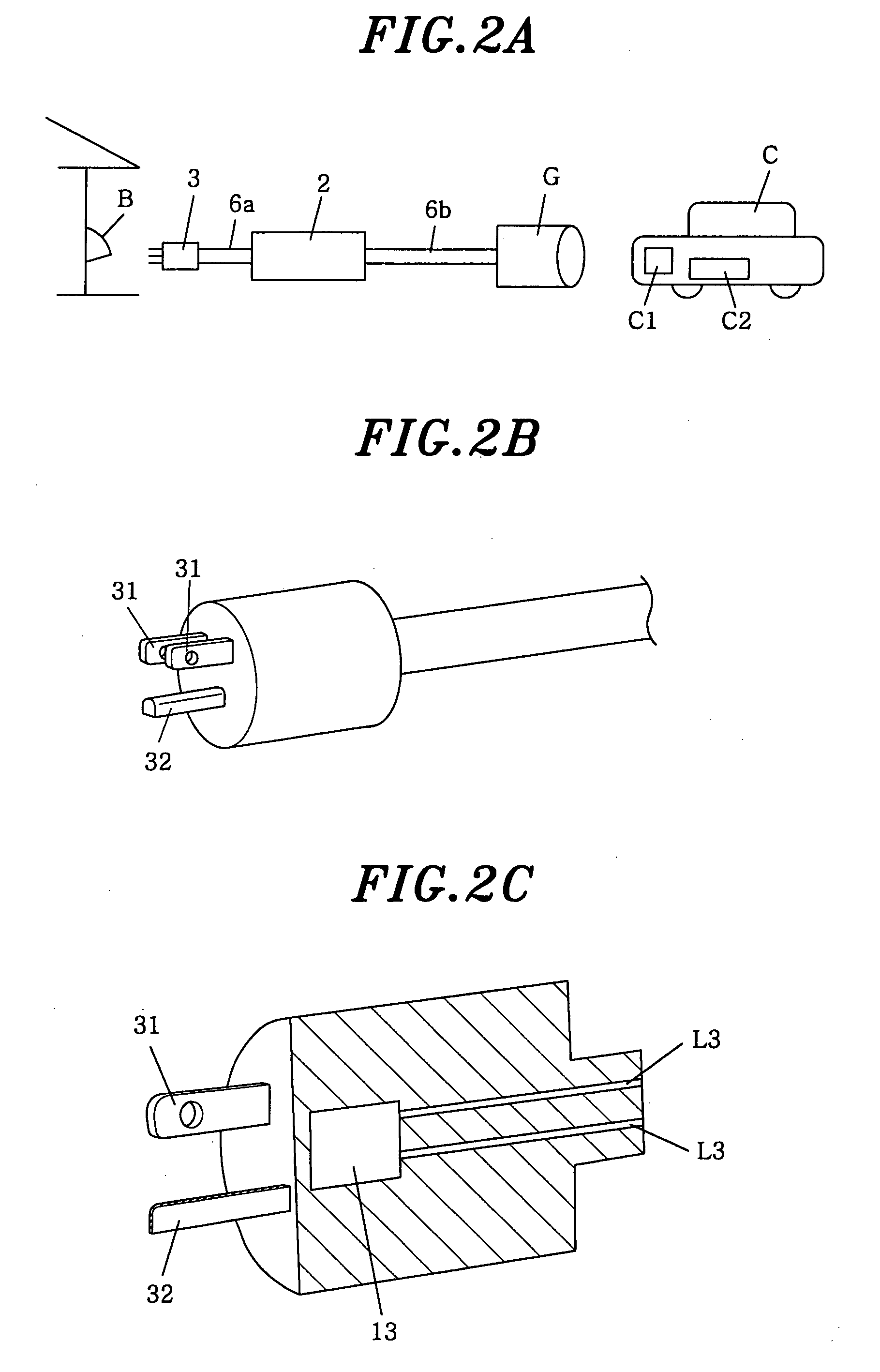
[0052]FIG. 1 is a schematic circuit diagram of a charging cable for an electric vehicle in accordance with the first embodiment of the present invention. FIG. 2A shows an example in which the charging cable is used to charge a battery to be used for driving an electric vehicle, FIG. 2B shows main parts of a plug of the charging cable, and FIG. 2C is a cross-sectional view thereof.

[0053]A charging cable A for an electric vehicle is, as shown in FIG. 2A, connected between a power outlet socket B provided on an outside wall of a house and a vehicle connector C1 of an electric vehicle C parked in a parking space outside the house to charge a driving battery C2 mounted on the electric vehicle C.

[0054]The power outlet socket B is of, e.g., a fall-out prevention structure for preventing a power plug from falling out because of its weight, and also has a waterproof s...

Example

Second Embodiment

[0066]Hereinafter, a second embodiment of the present invention will be described with reference to FIGS. 3A and 3B and FIGS. 4A and 4B. In this embodiment, same reference numerals are assigned to components same as those of the first embodiment and a description thereof will be omitted.

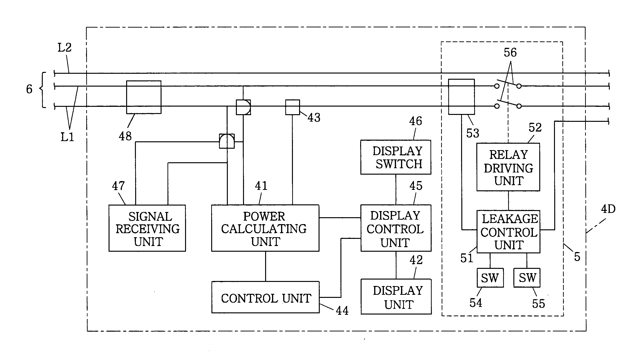
[0067]FIG. 3A is a schematic view of a system using a charging cable unit A1 of the second embodiment. The charging cable unit A1 of this embodiment includes a power plug 3, a cable connector G, and a display device 4. The power plug 3 is detachably connected to a power socket B (e.g., embedded socket, waterproof socket, or the like) which is supplied with, e.g., a commercial power source. The cable connector G is electrically connected to the power plug 3 via a power cable 6, and detachably connected to a connector (not shown) of an electric vehicle (an equipment to be powered) C which is supplied with a commercial power source to charge a secondary cell mounted therein. The displa...

Example

Third Embodiment

[0073]Hereinafter, a charging cable unit in accordance with a third embodiment of the present invention will be described with reference to FIGS. 5A to 5C and FIGS. 6A to 6D.

[0074]In the second embodiment, the integrated result (i.e., cumulative amount of power consumed in the charging of the electric vehicle C) of the power calculating unit 41 is displayed on the display unit 42, while this embodiment is different from the above in that electric charges or elapsed charging time, which is calculated on the basis of the integrated result, is displayed along with the integrated result on the display unit 42. Other configurations are the same as those of the second embodiment, and the same reference numerals are assigned to the same components so that a description of which will be omitted.

[0075]The display device 4A of the charging cable unit in accordance with the third embodiment includes, as shown in FIG. 5A, a power calculating unit 41, a display unit 42, a curren...


PUM


Abstract

A charging cable for an electric vehicle includes a power plug adapted to be detachably connected to a power socket of a commercial power source; a temperature detecting unit for detecting a temperature of the power plug; a cable connector adapted to be detachably connected to an electric vehicle for supplying a charging current to a battery of the electric vehicle; and a switching unit for opening and closing a current path between the power plug and the cable connector. The charging cable further includes a leakage detecting unit for detecting an electric leakage based on a current flowing through the current path; and a power cutoff unit for opening the switching unit when the detected temperature of the temperature detection means exceeds a threshold value or when the leakage detection means detects the electric leakage.

Description

FIELD OF THE INVENTION [0001]The present invention relates to a charging cable, a charging cable unit, and a charging system which are used to charge a battery of an electric vehicle.BACKGROUND OF THE INVENTION [0002]Recently, electric vehicles, including a hybrid car that runs on a combination of electric power stored in a secondary cell and fuel, such as gasoline, as a power source, and a secondary cell vehicle that runs on electric power stored in a secondary battery as a power source, have been put into practical use. These electric vehicles include an electric vehicle (for example, a plug-in hybrid car) whose battery is charged with electric power supplied from a commercial power source at a private home. For charging the battery, an electric vehicle charging cable is used in order to connect a socket outlet of the commercial power source and a connector of the electric vehicle.[0003]As this type of battery, there is included a battery requiring a high voltage of about, e.g., 2...

Claims


Application Information

Patent Timeline
IPC IPC(8): H02J7/02
CPCB60L3/0069B60L11/1818B60L11/1838B60L2230/12B60L2230/16Y02T90/163Y02T10/7005Y02T10/7088Y02T90/121Y02T90/128Y02T90/14B60L2240/36B60L53/16B60L53/18B60L53/305B60L53/66B60L53/62B60L53/68Y02T10/7072Y02T90/12Y02T90/16Y02T10/70
Inventor MUKAI, TATSUYAMINAMI, YOUJIUENO, SATORUGOTO, KIYOSHIMORI, SHIROWATANABE, HIROTOSHIKAKIUCHI, KOUJIOOYA, HIROSHIHAYASHI, TOMOYOSHITAKADA, YUTAKA
Owner PANASONIC CORP
Why Eureka
Try Eureka