Comparator circuit

a comparator circuit and circuit technology, applied in the field of comparator circuits, can solve the problems of limiting the bandwidth the capacitor connection between the comparator circuit and the offset error present in the comparator circuit, and the bandwidth limitation of the comparator circuit, so as to reduce the bandwidth, alleviate or eliminate one or more.

Inactive Publication Date: 2011-08-25
CSR TECH INC
View PDF6 Cites 8 Cited by
  • Summary
  • Abstract
  • Description
  • Claims
  • Application Information

AI Technical Summary

Benefits of technology

Accordingly, an object of the present invention is to mitigate, alleviate or eliminate one or more of the above-identified deficiencies and disadvantages.
It is an advantage of embodiments of the comparator circuit that an improved bandwidth is facilitated.

Problems solved by technology

Offset-errors are present in comparator circuits, e.g. due to mismatch between components, such as transistors, in the comparator circuits.
As a consequence, the first and the second switch provide a relatively high parasitic capacitive load to the comparator circuit, which may limit the bandwidth of the comparator circuit.
In addition, the capacitors connected between comparator circuits may also be a limiting factor for the bandwidth.
In an ADC, such a bandwidth limitation in a comparator circuit may limit the maximum sampling frequency of the ADC.

Method used


Image

  • Comparator circuit
  • Comparator circuit
  • Comparator circuit

Examples


Embodiment Construction

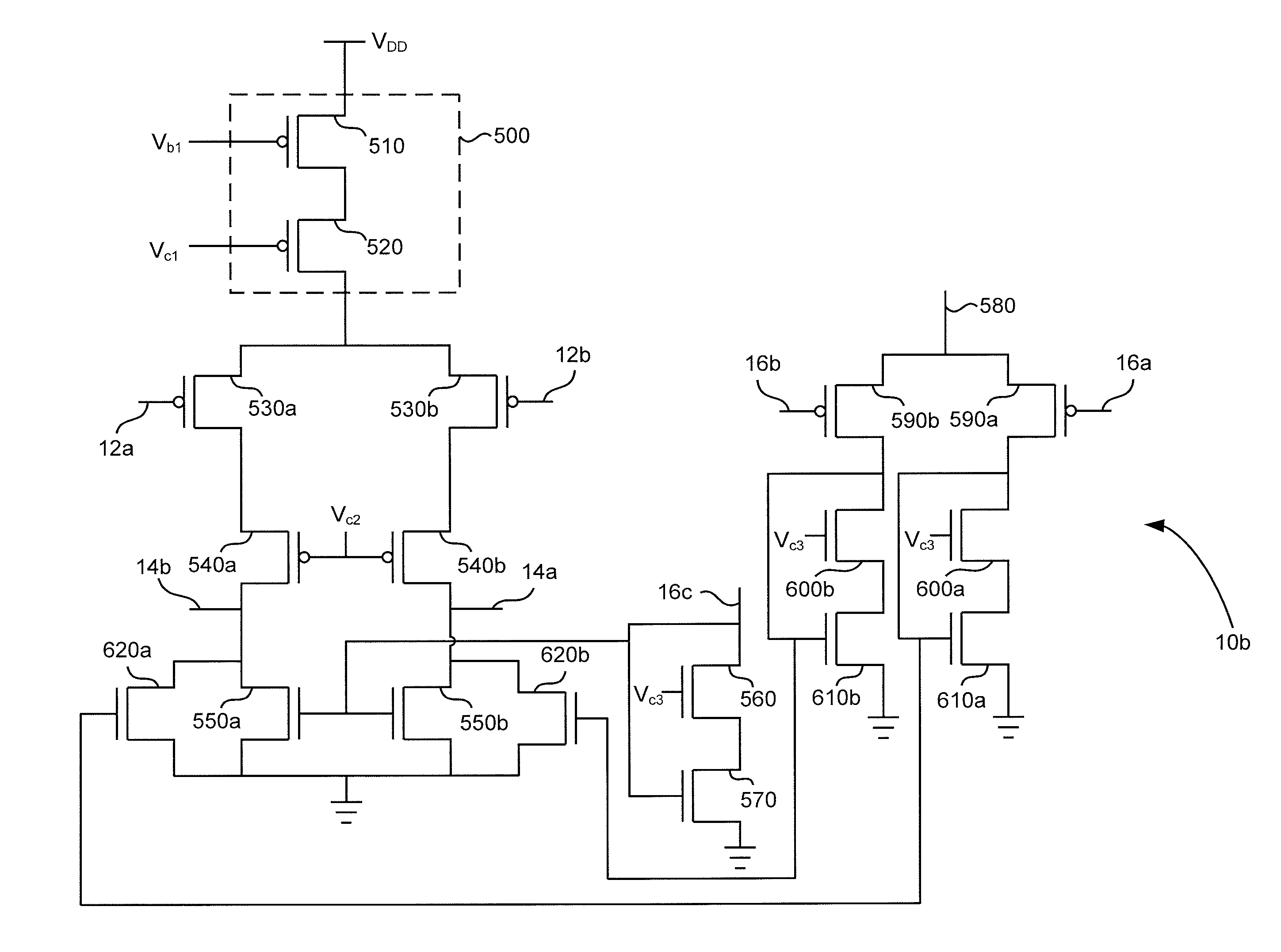
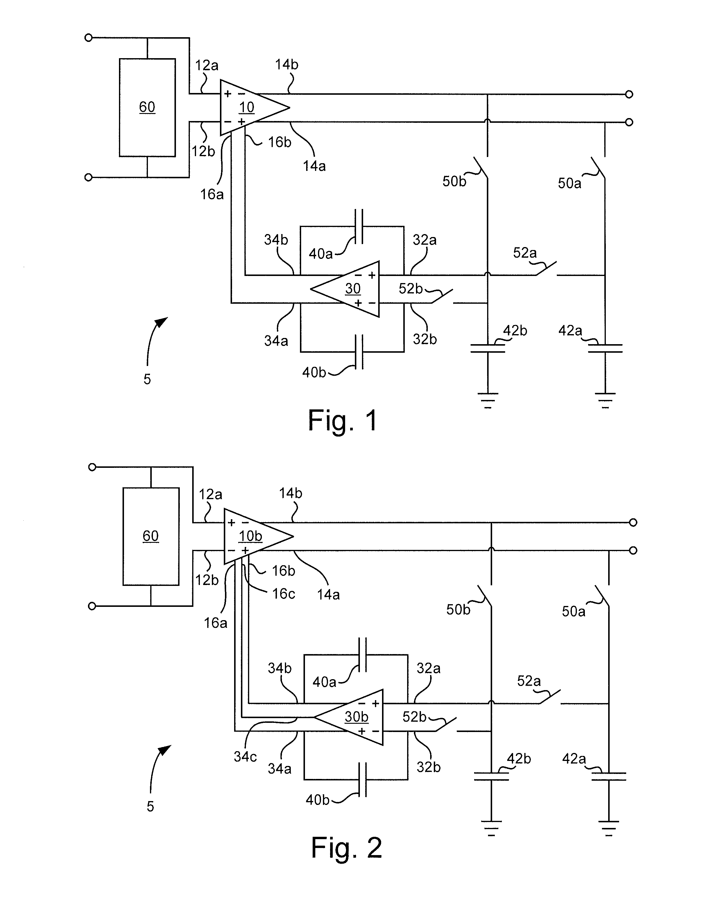
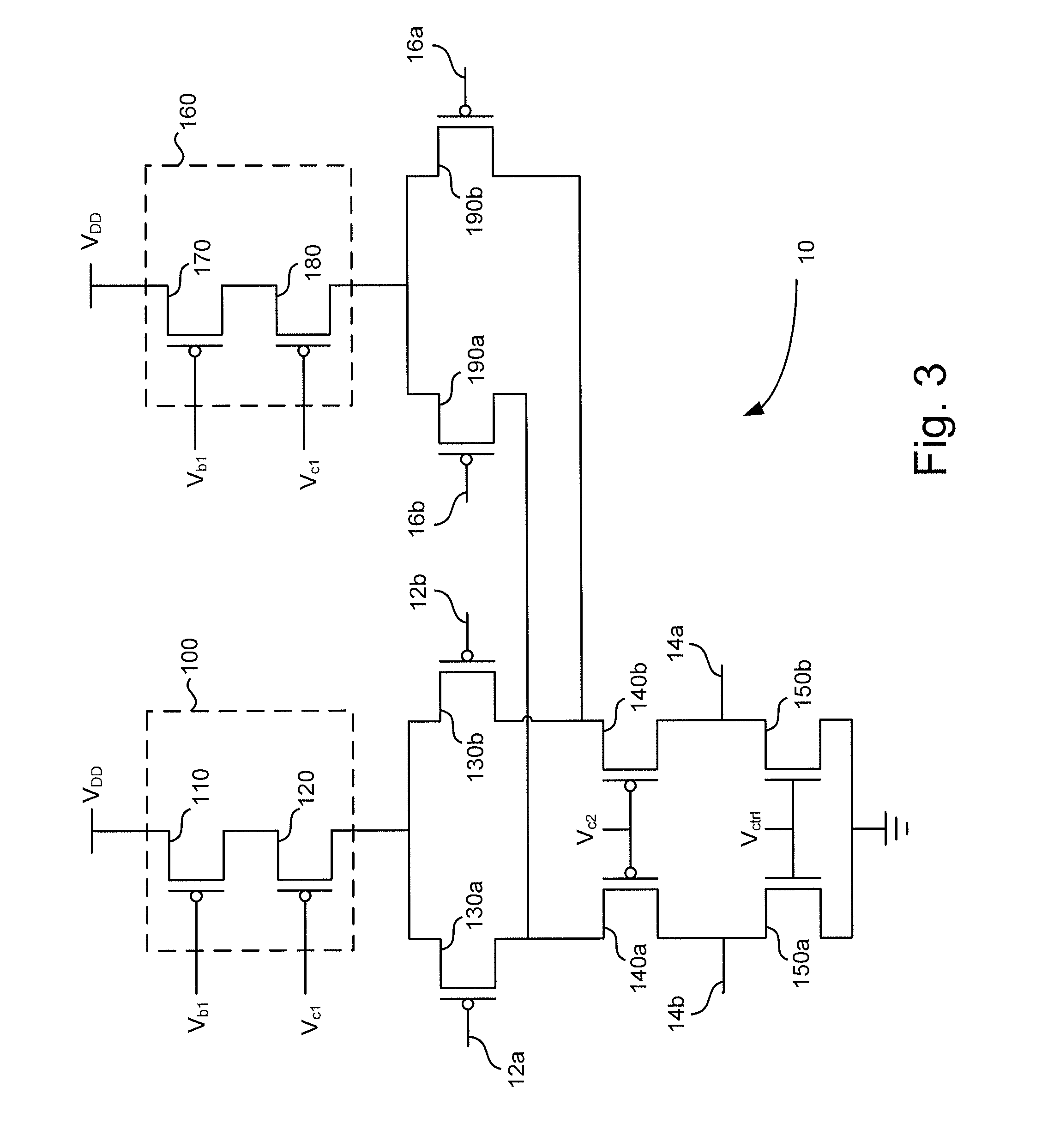
FIG. 1 is a circuit diagram of a comparator circuit 5 according to an embodiment. The comparator circuit 5, according to the embodiment, comprises a fully differential main amplifier unit 10. The main amplifier unit 10 has a positive input terminal 12a and a negative input terminal 12b for receiving a differential input signal of the comparator circuit 5. Furthermore, the main amplifier unit 10 has a positive output terminal 14a and a negative output terminal 14b for outputting a differential output signal of the comparator circuit 5. The positive output terminal 14a is associated with a first branch of the main amplifier unit 10, and the negative output terminal 14b is associated with a second branch of the main amplifier unit 10, as will be further elucidated with detailed embodiments of the main amplifier unit 10 and 10b (FIG. 2).

The main amplifier unit 10 comprises a first control terminal 16a and a second control terminal 16b. Furthermore, the main amplifier unit 10 is adapted ...


PUM


Abstract

A comparator circuit (5) comprising a fully differential main amplifier unit (10, 10b). The main amplifier unit (10, 10b) comprises a control port and is adapted to control a bias current of a first branch of the main amplifier unit (10, 10b) and / or a bias current of a second branch of the main amplifier unit (10, 10b) in response to one or more control voltages supplied to the control port of the main amplifier unit (10, 10b). The comparator circuit (5) comprises circuitry (60) for balancing the voltages at the positive and negative input terminals (12a, 12b) of the main amplifier unit (10, 10b) during a first clock phase of the comparator circuit (5). Furthermore, the comparator circuit (10, 10a) comprises a switched-capacitor accumulator unit with a differential input. The switched-capacitor accumulator unit is operatively connected to the positive and negative output terminals (14a, 14b) of the main amplifier unit (10, 10b) for sampling voltages at the positive and negative output terminals (14a, 14b) of the main amplifier unit (10, 10b) during the first clock phase, and operatively connected to the control port of the main amplifier unit (10, 10b) for supplying said one or more control voltages.

Description

TECHNICAL FIELDThe present invention relates to a comparator circuit.BACKGROUNDComparator circuits are used in electronic circuits e.g. to compare a first and a second voltage to determine which one of the first and the second voltage is the largest. For example, in an analog-to-digital converter (ADC), one or more comparator circuits may be used to compare an analog input voltage, or a voltage derived therefrom, with one or more reference-voltage levels in order to generate a digital output value corresponding to the analog input voltage.Offset-errors are present in comparator circuits, e.g. due to mismatch between components, such as transistors, in the comparator circuits. A process known as auto zeroing may be used to compensate for the offset-errors. For example, a first switch (e.g. MOS transistor) may be connected between the positive input terminal and the negative output terminal of a fully differential comparator circuit. In addition, a second switch may be connected betwe...

Claims


Application Information

Patent Timeline
Patent Type & Authority Applications(United States)
IPC IPC(8): H03F3/45
CPCH03F3/45753H03F2203/45292H03F2203/45634H03F2203/45538H03F2203/45444
Inventor JANSSON, CHRISTER
Owner CSR TECH INC
Why Eureka
Try Eureka