R-Fe-B ANISOTROPIC SINTERED MAGNET

a sintered magnet and anisotropic technology, applied in the field of r-fe-b based anisotropic sintered magnets, can solve the problems of not being heated sufficiently by normal resistance heating process, not easy to obtain expected crystal structure, etc., and achieve the effects of reducing the remanence br, increasing the coercivity hcj, and increasing the anisotropy of magnetocrystalline anisotropy

Active Publication Date: 2011-08-25
HITACHI METALS LTD
View PDF9 Cites 15 Cited by
  • Summary
  • Abstract
  • Description
  • Claims
  • Application Information

AI Technical Summary

Benefits of technology

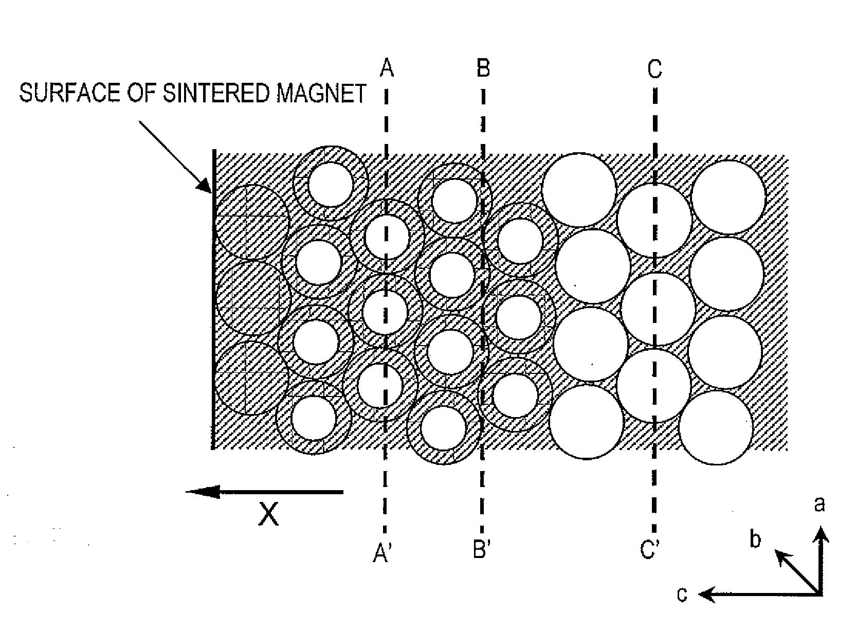
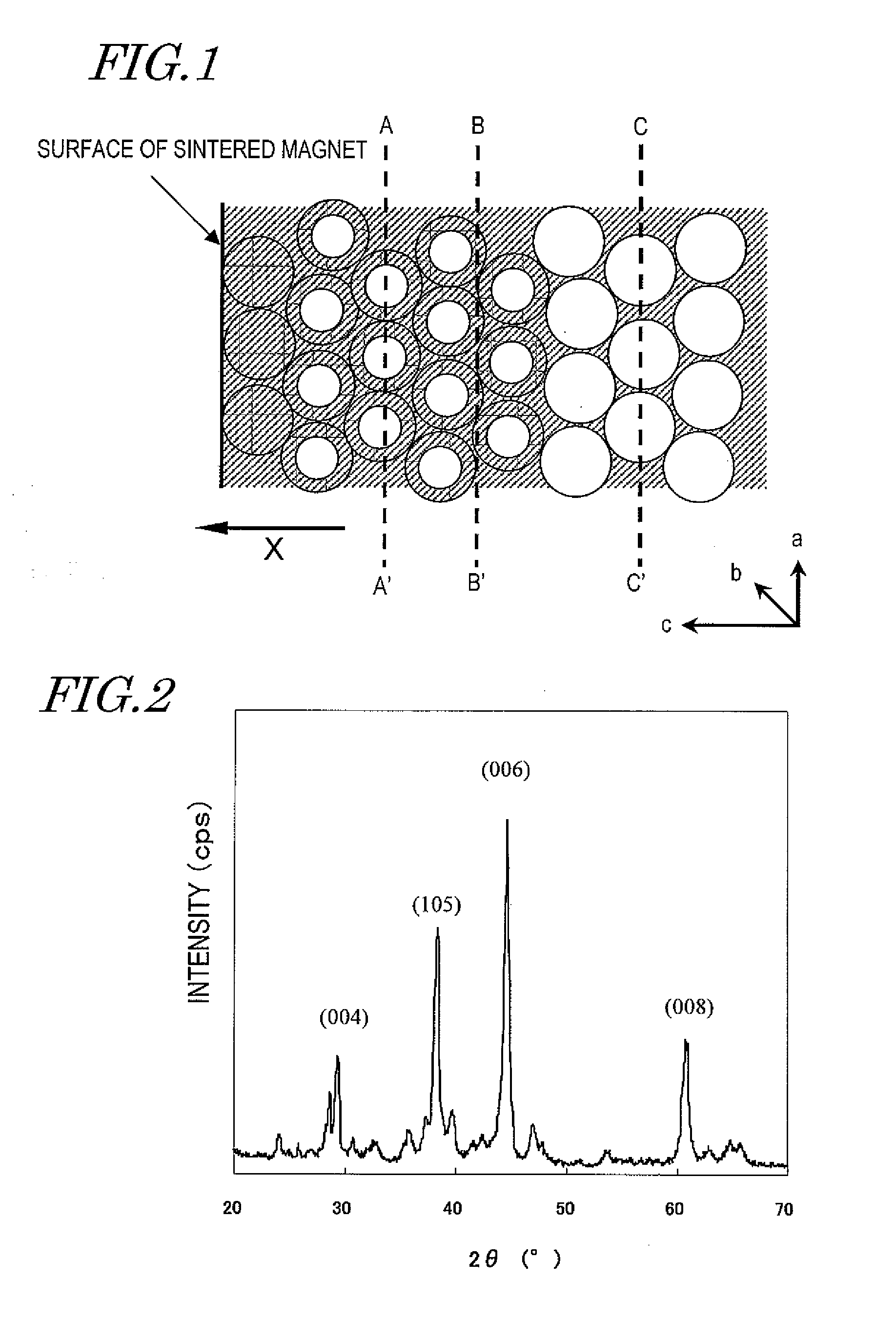
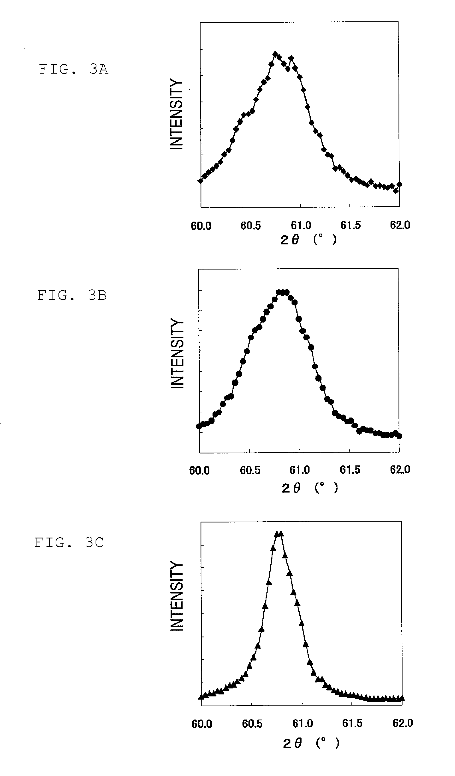
[0030]According to the present invention, the magnet includes a portion in which at least two peaks of diffraction are observed within a 2θ range of 60.5 degrees to 61.5 degrees when an X-ray diffraction measurement is carried out using a CuK a ray on a plane that is located at a depth of 500 μm or less under the surface (i.e., a pole face) of the sintered body and that is parallel to the pole face. Those two peaks indicate the presence of two regions in which the heavy rare-earth element RH has distinctly different concentrations. If those two peaks are observed in a relatively shallow region under the surface of the sintered body (i.e., in a surface region), then it means that there are a portion including a heavy rare-earth element RH in a relatively high concentration (corresponding to the outer periphery of a main phase grain) and a portion including the heavy rare-earth element RH in a relatively low concentration (corresponding to the core of the main phase grain) within each main phase. By realizing such a structure, the magnetocrystalline anisotropy can be increased preferentially in the outer periphery of the main phase grain and the coercivity HcJ can be increased as a result. That is to say, since a layer including RH in an increased concentration can be formed in the outer periphery of the main phase grain by using just a small amount of heavy rare-earth element RH, the decrease in remanence Br can be minimized and the coercivity HcJ can be increased.

Problems solved by technology

For that reason, it is not easy to obtain the expected crystal structure in which the heavy rare-earth element RH is included in increased concentrations in only the outer periphery of the main phase.
However, Dy has a boiling point of 2,560° C. According to Patent Document No. 5, Yb with a boiling point of 1,193° C. should be heated to a temperature of 800° C. to 850° C. but could not be heated sufficiently by normal resistance heating process.

Method used


Image

  • R-Fe-B ANISOTROPIC SINTERED MAGNET
  • R-Fe-B ANISOTROPIC SINTERED MAGNET
  • R-Fe-B ANISOTROPIC SINTERED MAGNET

Examples


embodiment

[0119]First, an alloy including 25 mass % to 40 mass % of a rare-earth element R, 0.6 mass % to 1.6 mass % of B (boron) and Fe and inevitably contained impurities as the balance is provided. A portion (at 10 mass %) of R may be replaced with a heavy rare-earth element RH, a portion of B may be replaced with C (carbon), and a portion (at most 50 at %) of Fe may be replaced with another transition metal element such as Co or Ni. For various purposes, this alloy may contain about 0.01 mass % to about 1.0 mass % of at least one additive element M that is selected from the group consisting of Al, Si, Ti, V, Cr, Mn, Ni, Cu, Zn, Ga, Zr, Nb, Mo, Ag, In, Sn, Hf, Ta, W, Pb and Bi.

[0120]Such an alloy is preferably made by quenching a melt of a material alloy by strip casting, for example. Hereinafter, a method of making a rapidly solidified alloy by strip casting will be described.

[0121]First, a material alloy with the composition described above is melted by induction heating within an argon ...

example 1

[0141]First, as shown in the following Table 1 (where the unit is mass %), thin alloy flakes having a composition including 0 to 10 mass % of Dy and an average thickness of 0.2 mm to 0.3 mm were made by strip casting process:

TABLE 1AlloyNdDyBCoAlCuFea32.001.000.900.150.10bal.b29.52.5c27.05.0d24.57.5e22.010.0

[0142]Next, a vessel was loaded with those thin alloy flakes and then introduced into a hydrogen pulverizer, which was filled with a hydrogen gas atmosphere at a pressure of 500 kPa. In this manner, hydrogen was absorbed into the thin alloy flakes at room temperature and then desorbed. By performing such a hydrogen process, the thin alloy flakes were decrepitated to obtain a powder in indefinite shapes with a size of about 0.15 mm to about 0.2 mm.

[0143]Thereafter, 0.04 wt % of zinc stearate was added to the coarsely pulverized powder obtained by the hydrogen process and then the mixture was pulverized with a jet mill to obtain a fine powder with a size of approximately 3 μm.

[0144...

example 2

[0157]First, thin alloy flakes g to i were made by strip casting process so as to have the compositions shown in the following Table 6 (where the unit is mass %) and an average thickness of 0.2 mm to 0.3 mm:

TABLE 6AlloyNdPrDyTbBCoAlCuFeg26.06.0001.000.900.150.10bal.h21.06.05.00i21.06.005.0

[0158]Next, a vessel was loaded with those thin alloy flakes and then introduced into a hydrogen pulverizer, which was filled with a hydrogen gas atmosphere at a pressure of 500 kPa. In this manner, hydrogen was absorbed into the thin alloy flakes at room temperature and then desorbed. By performing such a hydrogen process, the thin alloy flakes were decrepitated to obtain a powder in indefinite shapes with a size of about 0.15 mm to about 0.2 mm.

[0159]Thereafter, 0.04 wt % of zinc stearate was added to the coarsely pulverized powder obtained by the hydrogen process and then the mixture was pulverized with a jet mill to obtain a fine powder with a powder particle size of approximately 3 μm.

[0160]Th...


PUM

PropertyMeasurementUnit
depthaaaaaaaaaa
aaaaaaaaaa
areaaaaaaaaaaa

Abstract

An R—Fe—B based anisotropic sintered magnet according to the present invention has, as a main phase, an R2Fe14B type compound that includes a light rare-earth element RL (which is at least one of Nd and Pr) as a major rare-earth element R, and also has a heavy rare-earth element RH (which is at least one element selected from the group consisting of Dy and Tb). In the crystal lattice of the main phase, the c-axis is oriented in a predetermined direction. The magnet includes a portion in which at least two peaks of diffraction are observed within a 2θ range of 60.5 degrees to 61.5 degrees when an X-ray diffraction measurement is carried out using a CuK α ray on a plane that is located at a depth of 500 μm or less under a pole face of the magnet and that is parallel to the pole face.

Description

TECHNICAL FIELD[0001]The present invention relates to an R—Fe—B based anisotropic sintered magnet including an R2Fe14B type compound (where R is a rare-earth element) as a main phase. More particularly, the present invention relates to an R—Fe—B based anisotropic sintered magnet, which includes a light rare-earth element RL (which is at least one of Nd and Pr) as a major rare-earth element R and in which a portion of the light rare-earth element RL is replaced with a heavy rare-earth element RH (which is at least one element selected from the group consisting of Dy and Tb).BACKGROUND ART[0002]An R—Fe—B based anisotropic sintered magnet, including an Nd2Fe14B type compound phase as a main phase, is known as a permanent magnet with the highest performance, and has been used in various types of motors such as a voice coil motor (VCM) for a hard disk drive and a motor for a hybrid car and in numerous types of consumer electronic appliances. When used in motors and various other devices,...

Claims


Application Information

Patent Timeline
Patent Type & Authority Applications(United States)
IPC IPC(8): H01F1/053H01F7/02
CPCB22F2999/00C22C33/0257C22C38/005C22C2202/02H01F41/0293H01F1/0577B22F2207/01H01F1/053H01F1/08B22F3/24
Inventor ODAKA, TOMOORIMORIMOTO, HIDEYUKIYOSHIMURA, KOHSHITAKAKI, SHIGERU
Owner HITACHI METALS LTD
Why Eureka
Try Eureka