Resin-sealed electronic control device and method of fabricating the same

a technology of electronic control device and resin seal, which is applied in the direction of anti-theft device, semiconductor/solid-state device details, lighting and heating apparatus, etc., can solve the problems of affecting the quality of electronic control device. , to achieve the effect of increasing the area

Active Publication Date: 2011-08-25
MITSUBISHI ELECTRIC CORP
View PDF7 Cites 10 Cited by
  • Summary
  • Abstract
  • Description
  • Claims
  • Application Information

AI Technical Summary

Benefits of technology

[0016]The present invention has been made to solve the problems described above, and therefore, it is an object of the present invention to provide a low-cost small resin-sealed electronic control device in which at least one of two electronic boards serving as wiring boards bonded to two surfaces of a support member is a double-sided mounting board so as to increase an area on which circuit components are mounted, and a method of fabricating the same.
[0017]It is another object of the present invention to provide a low-cost small resin-sealed electronic control device in which the electronic boards including the double-sided mounting board are configured to perform one of thermal diffusion and heat dissipation through an intermediation of the separate beam members serving as the support member and a method of fabricating the same.
[0020]According to the resin-sealed electronic control device of the present invention, the separate beam members serve as the support member and a thermal diffuser member at the same time. In addition, the separate beam members ensure the distance between the first electronic board and the second electronic board to enable the mounting on two surfaces of each of the electronic boards. The circuit components mounted on the two surfaces of each of the electronic boards are arranged between the separate beam members. As a result, a mounting area is increased without increasing a plane area of each of the electronic boards. As a result, the present invention has the effects of reducing a plane area and a volume of the entire product.
[0021]Moreover, the heat-generating components mounted on the electronic boards are adjacent to and opposed to the separate beam members with the adhesives interposed therebetween and have the effects of preventing the temperature from being locally and extremely increased by thermal diffusion.
[0022]Moreover, a space between the first electronic board and the second electronic board is filled with the exterior covering material to provide a non-hollow structure. As a result, the electronic boards can be prevented from being deformed at the time of pressure-molding of the synthetic resin. Moreover, the effects of preventing the separation of a solder of the mounted circuit components and the separation between the electronic boards and the support member or the exterior covering material due to expansion and shrinkage of the air with a change in environmental temperature during actual use.

Problems solved by technology

Therefore, in order to ensure an area on which the circuit components are mounted, the area of each of the wiring boards is disadvantageously increased.
Moreover, if the area of each of the wiring boards is large, there is another problem in that the wiring board is likely to be separated from a molded exterior covering material with repeating changes in temperature due to a difference in linear expansion coefficient.
Further, if the heat-generating circuit components are provided on both the upper surface and the lower surface of the thermal diffuser plate, there is a further problem in that the temperature increases in a locally concentrated manner.
Therefore, there is a problem in that an area of each of the wiring boards is increased.
In addition, a complex cooling-medium flow path for cooling the entire surfaces of the wiring boards is required.
Thus, there is another problem in that a specific one of the heat-generating components cannot be cooled in a focused way.

Method used


Image

  • Resin-sealed electronic control device and method of fabricating the same
  • Resin-sealed electronic control device and method of fabricating the same
  • Resin-sealed electronic control device and method of fabricating the same

Examples


first embodiment

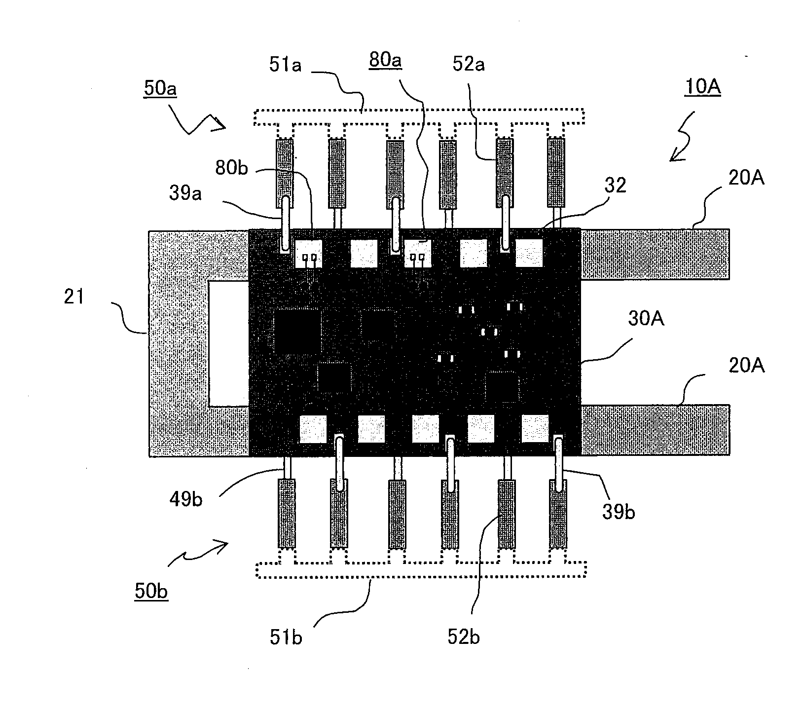
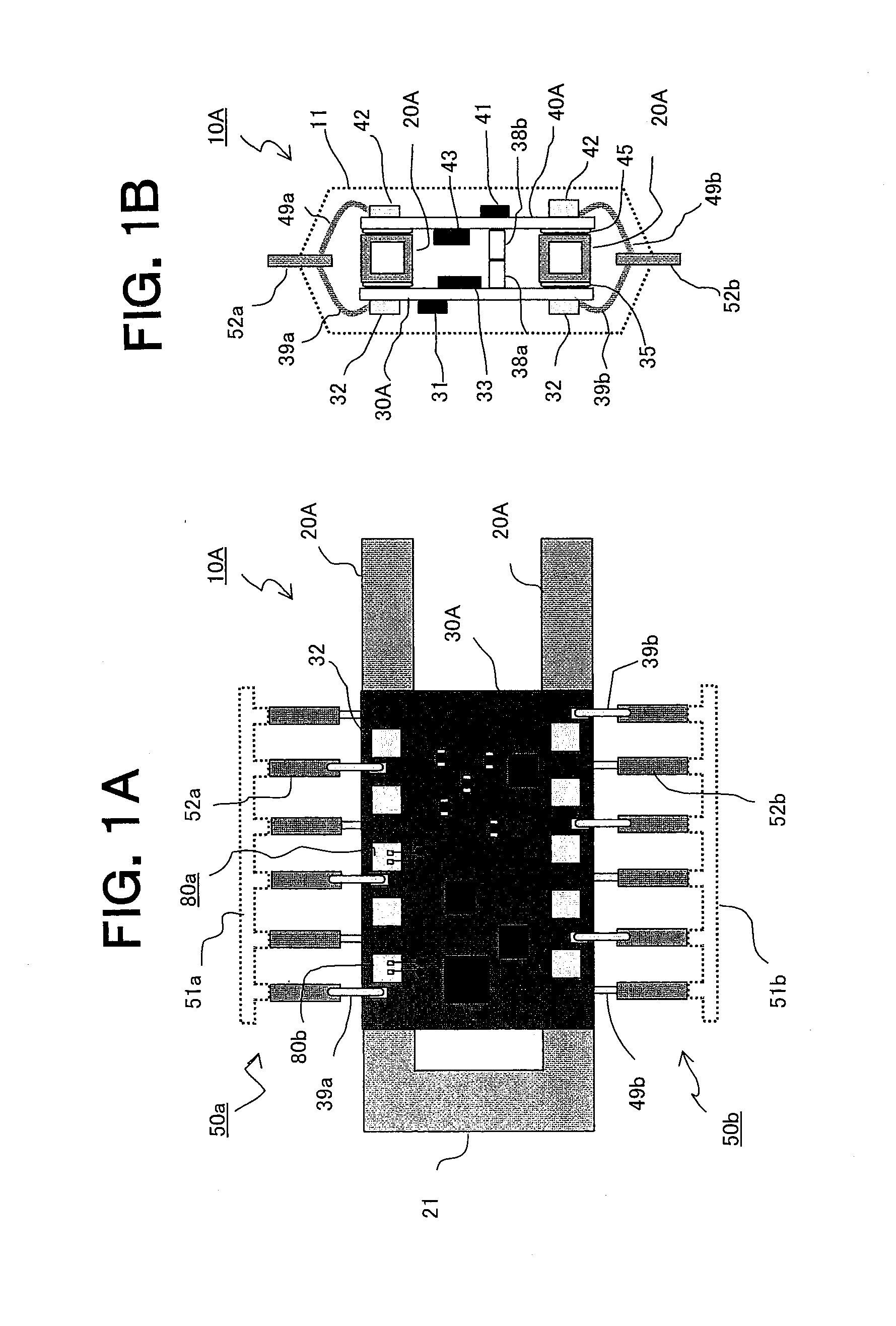
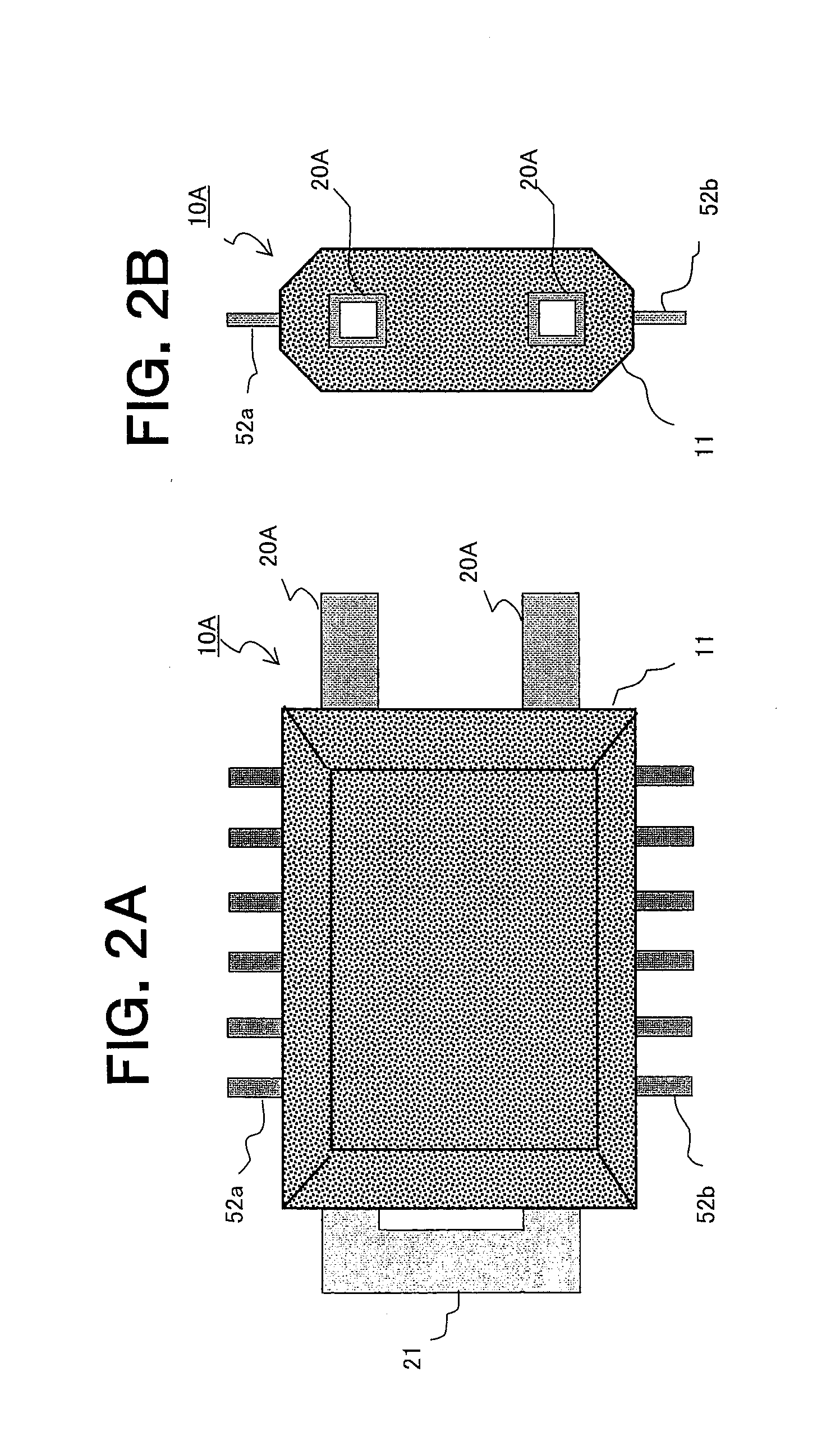
[0046]FIG. 1A is a top view of a resin-sealed electronic control device (hereinafter, abbreviated as “electronic control device”) according to a first embodiment of the present invention, and FIG. 1B is a right side view of FIG. 1A. FIG. 2A is another top view of the electronic control device according to the first embodiment of the present invention, and FIG. 2B is a right side view of FIG. 2A.

[0047]An electronic control device 10A, which is a transmission control device for an automobile transmission, includes: a pair of separate beam members 20A; a first electronic board 30A; a second electronic board 40A; a plurality of external connection terminals 52a and 52b; and an exterior covering material 11. The separate beam members 20A serve as hollow cylindrical thermally-conductive support members made of, for example, a copper alloy. One end of one of the separate beam members 20A is connected to one end of the other separate beam member 20A through a connection portion 21. The firs...

second embodiment

[0100]FIG. 8A is a top view of an electronic control device 10B according to a second embodiment of the present invention before sealing with a resin, and FIG. 8B is a right side view of FIG. 8A. FIG. 9A is a top view of the electronic control device 10B according to the second embodiment of the present invention, and FIG. 9B is a right side view of FIG. 9A.

[0101]The electronic control device 10B is a drive control device for a radiator fan which constitutes a part of a water-cooled automobile engine control device. The electronic control device 10B includes: a pair of separate beam members 20B; connection plates 22a and 22b; a first electronic board 30B; a second electronic board 40B; the plurality of external connection terminals 52a and 52b; and the exterior covering material 11. The pair of separate beam members 20B are hollow cylindrical thermally conductive support members made of, for example, a copper alloy. The connection plates 22a and 22b are bonded onto surfaces of each ...

third embodiment

[0134]FIG. 13A is a top view of an electronic control device 100 according to a third embodiment of the present invention before sealing with a resin, and FIG. 13B is a right side view of FIG. 13A. FIG. 14A is a top view of the electronic control device 10C according to the third embodiment of the present invention, and FIG. 14B is a right side view of FIG. 14A.

[0135]The electronic control device 10C is a transmission control device for an automobile transmission. The electronic control device 10C includes: a pair of separate beam members 20C; connection plates 22c and 22d; a first electronic board 30C; a second electronic board 40C; a plurality of external connection terminals 55c, 55d, 56c, and 56d; flexible boards 54a and 54b; and the exterior covering material 11. The pair of separate beam members 20C are hollow cylindrical thermally conductive support members made of, for example, a copper alloy. The connection plates 22c and 22d are respectively bonded onto two surfaces of eac...


PUM

PropertyMeasurementUnit
areaaaaaaaaaaa
thermally conductiveaaaaaaaaaa
height sizeaaaaaaaaaa

Abstract

Provided is a resin-sealed electronic control device reduced in size, which includes a double-sided mounting board as at least one of a plurality of electronic boards obtained by division so that a large mounting surface with a small plane area is ensured. Each of a first electronic board (30A) and a second electronic board (40A) bonded onto an upper surface and a lower surface of each of a pair of separate beam members (20A) includes two surfaces on which outer circuit components (31, 32, 41, 42) and an inner circuit component (33, 43) are respectively mounted. A height of each of the inner circuit components is equal to or less than a thickness of each of the separate beam members (20A). Heat-generating components (32, 42) in the outer circuit components are provided to be adjacent to and opposed to the separate beam members (20A).

Description

BACKGROUND OF THE INVENTION[0001]1. Field of the Invention[0002]The present invention relates to a resin-sealed electronic control device used as an on-vehicle electronic control device, and a method of fabricating the same.[0003]2. Description of the Related Art[0004]As a control device for an automobile transmission, an integrated electronic control device mounted inside the transmission is widely put into practical use.[0005]The on-vehicle electronic control device as described above includes any one of a ceramic board and a polyimide board bonded to a support member serving as a thermal diffuser plate. The entire on-vehicle electronic control device except for a part of external connection terminals and a part of the support member is integrally formed with a thermosetting resin.[0006]For example, the invention entitled “Electronic Circuit Apparatus and Method of Manufacturing the Same”, which is described in Japanese Patent Application Laid-open No. 2004-281722 (FIG. 1 and Abst...

Claims


Application Information

Patent Timeline
Patent Type & Authority Applications(United States)
IPC IPC(8): H05K7/20B29C45/14
CPCB60R25/00F16H59/72H01L2924/01013H01L2924/01068H05K5/0082H01L2924/01078H01L2924/01014H01L2224/49175H01L2224/4903H01L2224/48247H01L2224/48091F16H61/0006H01L21/565H01L23/3677H01L23/473H01L23/49531H01L23/49575H01L24/32H01L24/45H01L24/48H01L24/49H01L25/162H01L2224/32014H01L2224/45124H01L2924/00014H01L2924/00H01L2924/181H01L2924/00012
Inventor KANZAKI, SHOZO
Owner MITSUBISHI ELECTRIC CORP
Why Eureka
Try Eureka