
Catheter Assembly with Valve Crimping Accessories

a technology for crimping accessories and catheter assemblies, which is applied in the direction of metal-working machine components, manufacturing tools, prostheses, etc., can solve the problems of user error, difficult positioning of crimping devices over catheter assemblies, and difficult removal of known crimping devices from catheter bodies, etc., to simplify the process of crimping

Active Publication Date: 2011-08-25
MEDTRONIC VENTOR TECH
View PDF14 Cites 90 Cited by
  • Summary
  • Abstract
  • Description
  • Claims
  • Application Information

AI Technical Summary

Benefits of technology

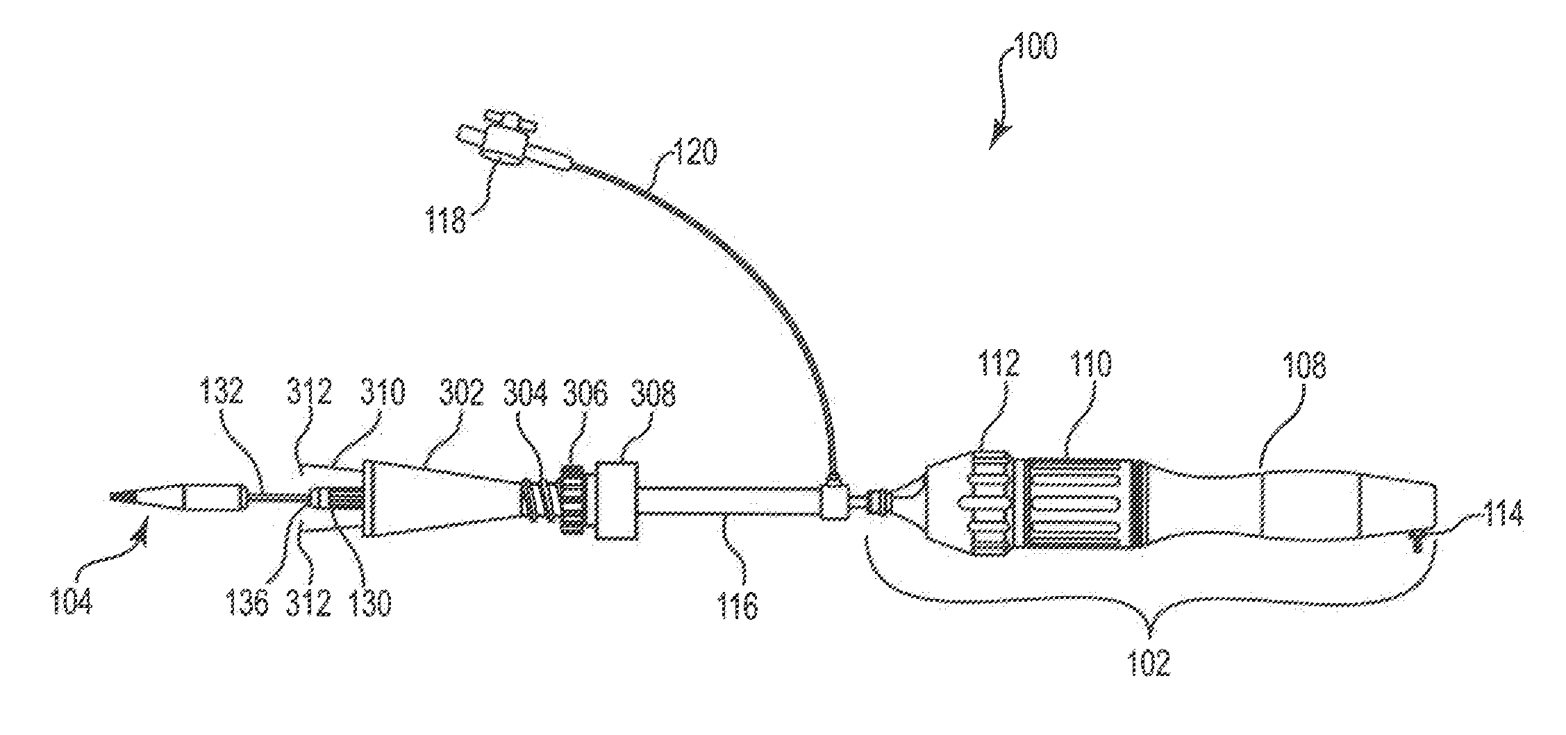
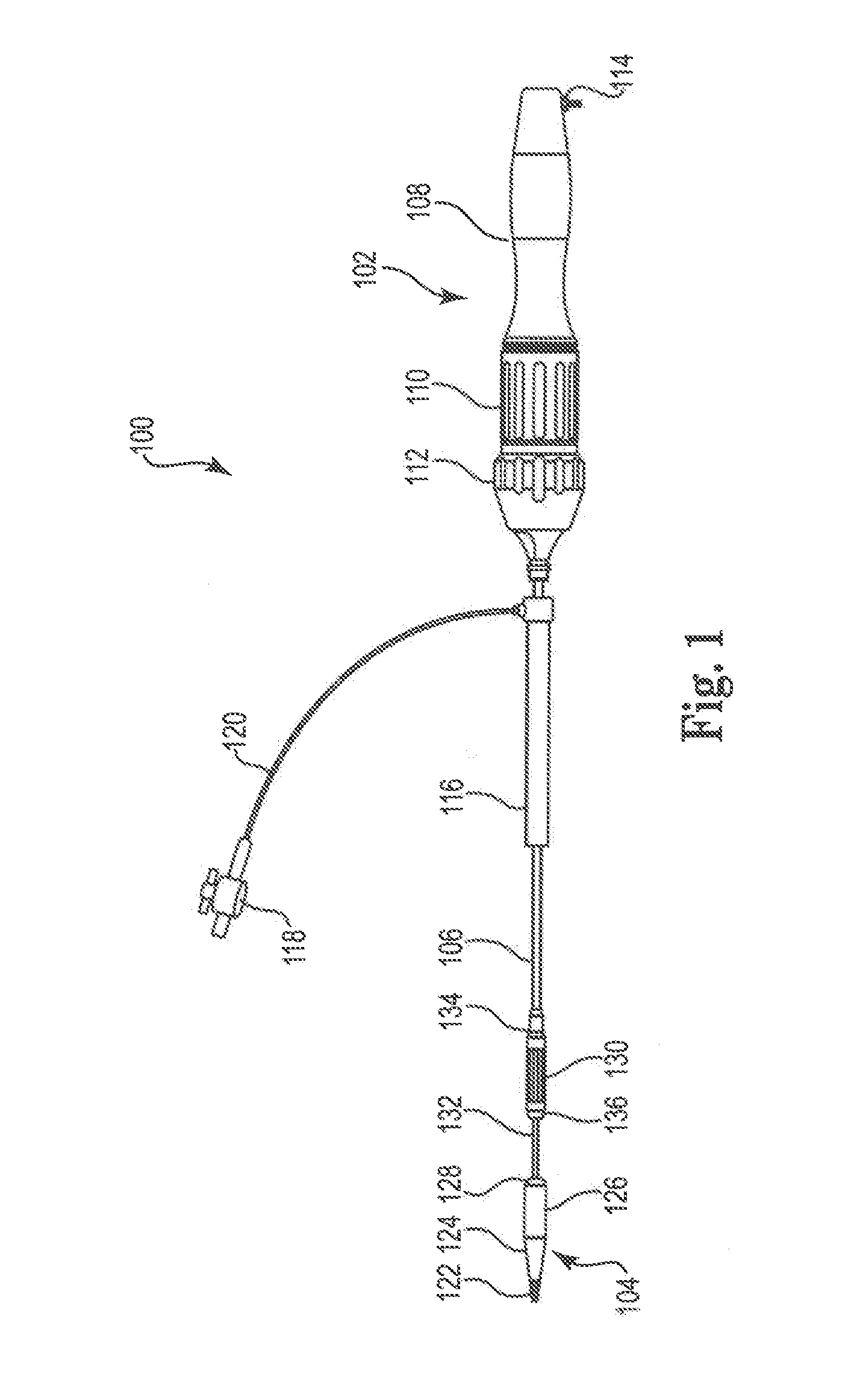
[0010]The catheter assemblies and crimping accessories and methods described herein seek to remedy one or more of the disadvantages of previous crimping methods by providing catheters and crimping accessories that simplify the process of crimping a prosthetic valve or stent to a catheter. The crimping accessories and methods described herein are particularly useful for crimping a prosthetic valve onto a catheter having a distal tip with a diameter larger than the final crimped diameter of the prosthetic valve. In one embodiment of the present invention, a catheter assembly includes a handle assembly located on the proximal end of the catheter assembly and a distal tip assembly located on the distal end of the catheter assembly. A crimping funnel is slidably positioned along the catheter. The crimping funnel includes a distal end having a first diameter and a proximal end having a second diameter smaller than the first diameter. An axial split is formed in the proximal end. A first collar is provided encompassing a portion of the proximal end. The first collar is configured to hold the axial split in the proximal end together when the first collar is at a first axial location along the proximal end, and to allow the axial split in the proximal end to open when the first collar is at a second axial location along the proximal end, such that the crimping funnel can be removed from the catheter assembly.

Problems solved by technology

However, crimping a prosthetic valve using known hand held or tabletop devices requires a user to assemble and position the crimping device over a separately acquired catheter, resulting in the possibility of user error.
In addition, positioning a crimping device over a catheter assembly can be complicated, for example, where the catheter assembly has a distal tip with a diameter larger than the final crimped diameter of the valve.
In such situations, the known crimping devices are difficult to position on and remove from the catheter body.

Method used


Image

  • Catheter Assembly with Valve Crimping Accessories
  • Catheter Assembly with Valve Crimping Accessories
  • Catheter Assembly with Valve Crimping Accessories

Examples


example 1

[0066]One embodiment of the present invention provides a catheter assembly for crimping an expandable prosthesis. The catheter assembly includes a handle assembly located on the proximal end of the catheter assembly and a distal tip assembly located on the distal end of the catheter assembly. A first elongate member is provided extending from the handle assembly towards the distal tip assembly. A crimping funnel is slidably positioned over the first elongate member. The crimping funnel includes a distal end having a first diameter and a proximal end having a second diameter smaller than the first diameter. An axial split is formed in the proximal end. A first collar is provided encompassing a portion of the proximal end. The first collar is configured to hold the axial split in the proximal end together when the first collar is at a first axial location along the proximal end, and to allow the axial split in the proximal end to open when the first collar is at a second axial locatio...

example 2

[0068]Another embodiment provides a method of crimping a prosthetic valve onto a catheter assembly. The method includes obtaining a catheter assembly including a first elongate member, a crimping funnel slidably positioned over the first elongate member, a valve retaining assembly positioned over the first elongate member, and a first sleeve positioned over the first elongate member. A prosthetic valve is then secured to the valve retaining assembly. The prosthetic valve is then crimped by advancing the crimping funnel in a distal direction along the first elongate member and over the first sleeve. The first sleeve is then advanced in a distal direction along the first elongate member until at least a proximal portion of the crimped prosthetic valve is encompassed by the first sleeve. Finally, the funnel is removed from the catheter assembly.

[0069]The obtained catheter assembly can also include a second sleeve positioned over the first elongate member distally of the first sleeve. T...


PUM

PropertyMeasurementUnit
diameteraaaaaaaaaa
sizeaaaaaaaaaa
structureaaaaaaaaaa

Abstract

Catheter assemblies including a handle assembly located on the proximal end of the catheter assembly and a distal tip assembly located on the distal end of the catheter assembly. A crimping funnel is slidably positioned along the catheter. The crimping funnel includes a distal end having a first diameter and a proximal end having a second diameter smaller than the first diameter. An axial split is formed in the proximal end. A first collar is provided encompassing a portion of the proximal end. The first collar is configured to hold the axial split in the proximal end together when the first collar is at a first axial location along the proximal end, and to allow the axial split in the proximal end to open when the first collar is at a second axial location along the proximal end, such that the crimping funnel can be removed from the catheter assembly. Various methods of retaining a prosthetic valve on the catheter assembly during the crimping process are described.

Description

CROSS REFERENCE TO RELATED APPLICATIONS[0001]This application claims the benefit of provisional patent application No. 61 / 307,731, filed Feb. 24, 2010,BACKGROUND[0002]1. Field of the Invention[0003]The present invention relates to catheter assemblies, crimping accessories, and methods of crimping prosthetic valves onto a catheter. More specifically, the present invention provides for catheters and crimping accessories that simplify the process of crimping a prosthetic valve to a catheter.[0004]2. Background[0005]Recently, minimally invasive approaches have been developed to facilitate catheter-based implantation of valve prostheses on the beating heart, intending to obviate the need for the use of classical sternotomy and cardiopulmonary bypass. For example, French Patent Application No. 99 14462 illustrates a technique and a device for the ablation of a deficient heart valve by percutaneous route, with a peripheral valvular approach. International Application (PCT) Nos. WO 93 / 01768...

Claims


Application Information

Patent Timeline
Patent Type & Authority Applications(United States)
IPC IPC(8): A61F2/24B23Q7/04
CPCA61F2/2427Y10T29/53996A61F2002/9522A61F2/95A61F2/9522A61F2002/9665A61F2/9525A61F2/2436
Inventor DUFFY, NIALLMEARNS, PAULGALLAGHER, JOHNMILLER, NOAM
Owner MEDTRONIC VENTOR TECH
Features
  • Generate Ideas
  • Intellectual Property
  • Life Sciences
  • Materials
  • Tech Scout
  • Unparalleled Data Quality
  • Higher Quality Content
  • 60% Fewer Hallucinations
Learn More