

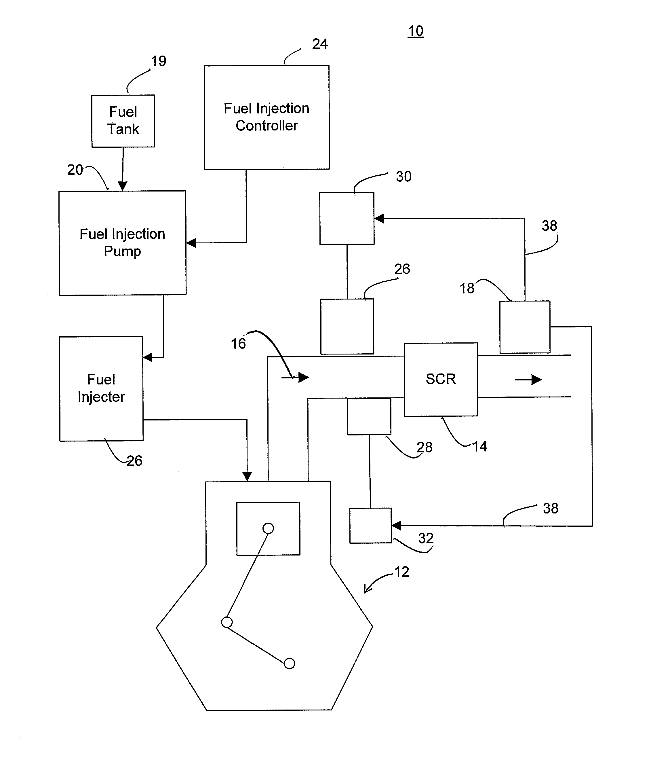
System and Method for Controlling Nitrous Oxide Emissions of an Internal Combustion Engine and Regeneration of an Exhaust Treatment Device
a technology of nitrous oxide emission and internal combustion engine, which is applied in the direction of engines, machines/engines, mechanical equipment, etc., can solve the problems of reducing conversion efficiency outside the temperature range, nox production, and sulfur dioxide emission
- Summary
- Abstract
- Description
- Claims
- Application Information
AI Technical Summary
Benefits of technology
Problems solved by technology
Method used
Image

Examples
example 1
Manufacture of a Catalyst Composition
[0072]The catalyst composition is designated as Sample Ag-(TX-114). An amount of TRITON X-114 surfactant serves as the templating agent. The catalyst composition is manufactured by making a first solution, a second solution and a third solution, which are mixed together.
[0073]The first solution includes ethyl acetoacetate (26.5 g, 0.2 mol), TRITON X-114 (139 g) and 2-butanol (500 mL). These are combined in a 5-L, 3-neck flask equipped with an addition funnel, a condenser, and a mechanical stirrer. The second solution includes aluminum sec-butoxide (Al(OsecBu)3) (500 g, 2 mol) and 2-butanol (2 L)). The second solution is added to the first solution with stirring and held at an ambient temperature for 30 minutes. The third solution includes water (75 mL, 4 mol), AgNO3 (10.2 g, 60 mmol) and 2-butanol (950 mL) and is added to the first and second solutions via the addition funnel over a period of about 90 minutes. The solutions are heated at ambient ...
example 2
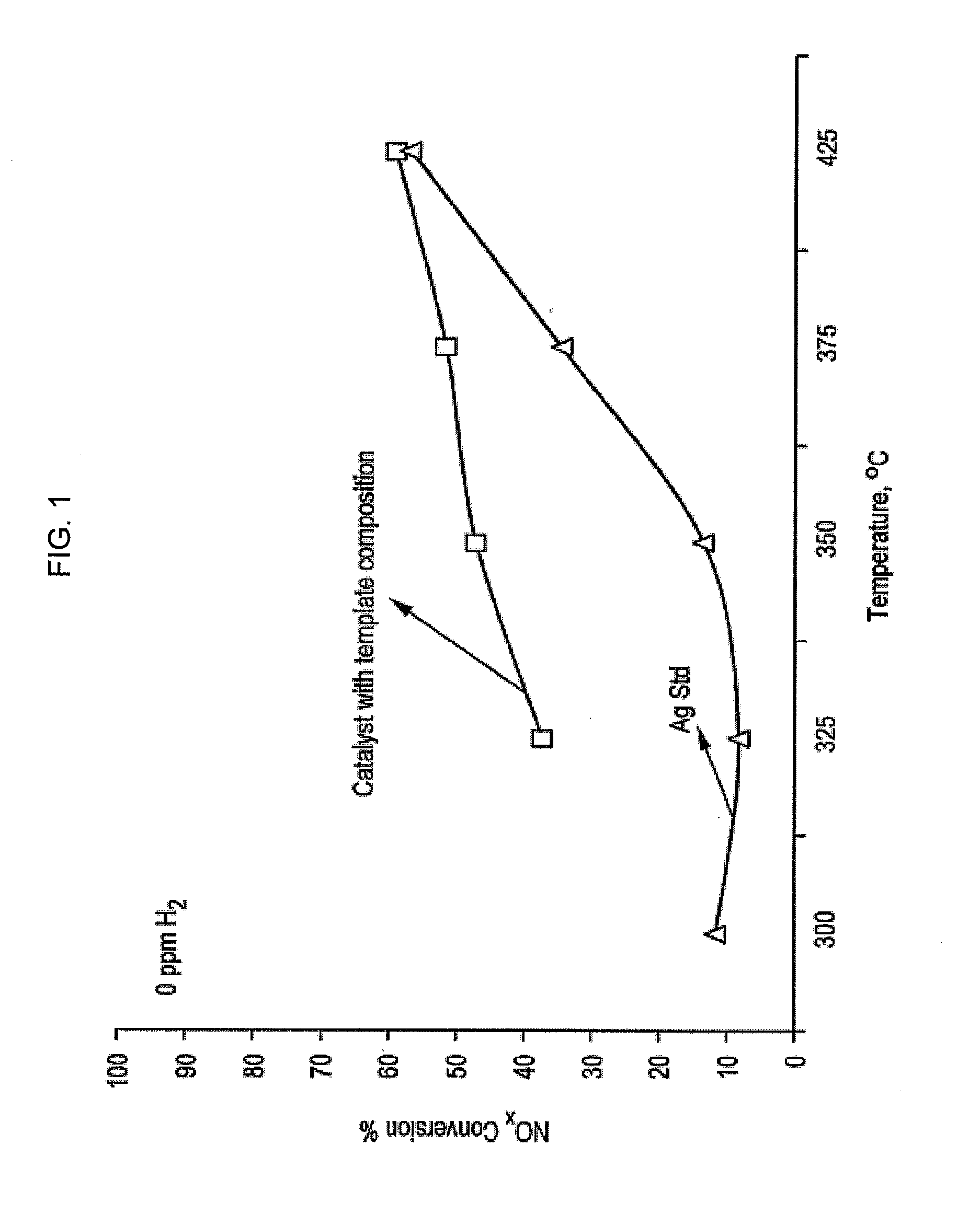
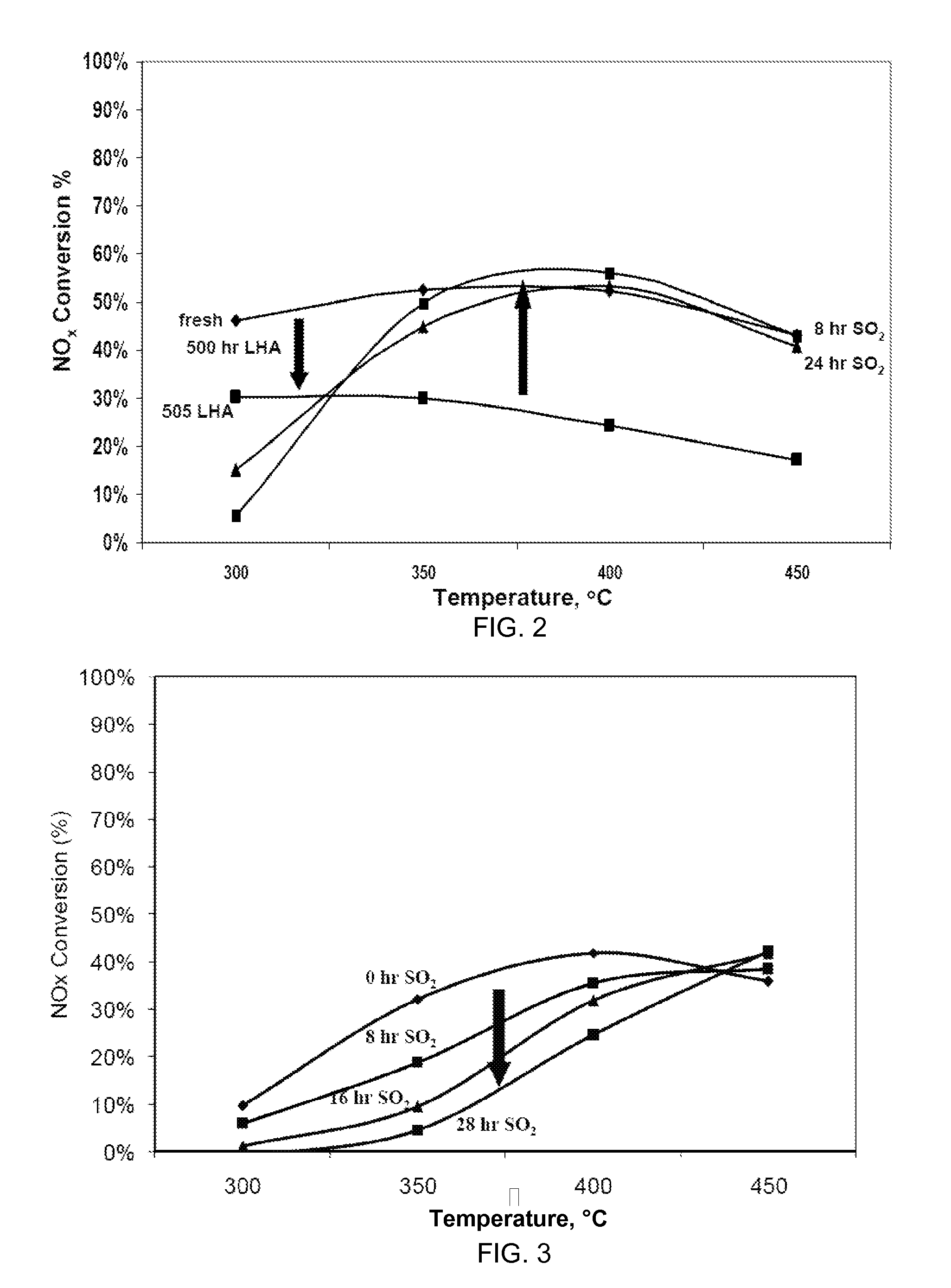
Performance of Catalyst Compositions
[0076]This example compares conversion performance of NOx contained in an exhaust gas streams for samples that include embodiments of the invention relative to comparative catalyst compositions. The comparative catalyst compositions do not contain substrates manufactured using a templating agent. This example demonstrates that the catalyst composition can be manufactured and used in the form of a monolith.
[0077]The water-based sol obtained from the synthesis as described in Example 1 was processed in a way conducive for washcoating. The aqueous sol was poured in a freeze-drying pan that was filled with liquid N2. The sol instantly froze forming porous foam. In order to ensure the sol does not melt during drying, the freeze-dryer was pre-frozen to −55° C. The freeze-dryer was slowly heated from −55° C. to +30° C. with 2 h isothermal hold after every 5° C. A pressure of 300 mTorr was maintained during the drying cycle. The resulting PSD after drying...
PUM
 Abstract
Description
Claims
Application Information