Combined type pressure gauge, and manufacturing method of combined type pressure gauge

a technology of pressure gauge and manufacturing method, which is applied in the direction of fluid pressure measurement, fluid pressure measurement by electric/magnetic elements, instruments, etc., can solve the problems of reducing manufacturing efficiency, increasing manufacturing costs, and inability to efficiently use the process of these gauges, so as to reduce manufacturing costs and reduce production costs , the effect of high accuracy

Active Publication Date: 2011-09-01
CANON ANELVA CORP
View PDF12 Cites 16 Cited by
  • Summary
  • Abstract
  • Description
  • Claims
  • Application Information

AI Technical Summary

Benefits of technology

[0010]The present invention has been made in view of the above problems involved in conventional combined type pressure gauges and manufacturing methods thereof, and aims at providing a combined type pressure gauge that reduces the manufacturing cost and has a reduced size, and the manufacturing method thereof.
[0013]The compound type pressure gauge according to the present invention can realize a pressure gauge having a small size and capable of measuring a wide range of pressure with a high accuracy. In more detail, the manufacturing method of the compound type pressure gauge according to the present invention allows manufacturing of a capacitive diaphragm pressure gauge and a Pirani pressure gauge on a single silicon substrate by a micromachining technology, which makes it possible to downsize products and to reduce the manufacturing cost by mass production. Moreover, in the process of manufacturing the combined type pressure gauge of the present invention, too, it is possible to process and manufacture simultaneously both pressure gauges, which makes it possible to design the manufacturing process to be common. Therefore, as compared with conventional processes in which respective pressure gauges are manufactured separately and, after that, are united and assembled, it becomes possible to shorten considerably the manufacturing process, which also makes it possible to obtain a large effect in terms of reducing the manufacturing cost.

Problems solved by technology

Moreover, since two pressure gauges are arranged in a small place, the lowering of manufacturing efficiency or, potentially, the lowering of yield is caused to thereby increase the manufacturing cost, occasionally.
Japanese Patent Application Laid-open Publication No. 2008-209284 does not disclose a specific manufacturing method of producing simultaneously a Pirani pressure gauge and a diaphragm pressure gauge on the same substrate.
Therefore, the processes to from these gauges cannot be efficient and the manufacturing cost cannot also be reduced.

Method used


Image

  • Combined type pressure gauge, and manufacturing method of combined type pressure gauge
  • Combined type pressure gauge, and manufacturing method of combined type pressure gauge
  • Combined type pressure gauge, and manufacturing method of combined type pressure gauge

Examples


Embodiment Construction

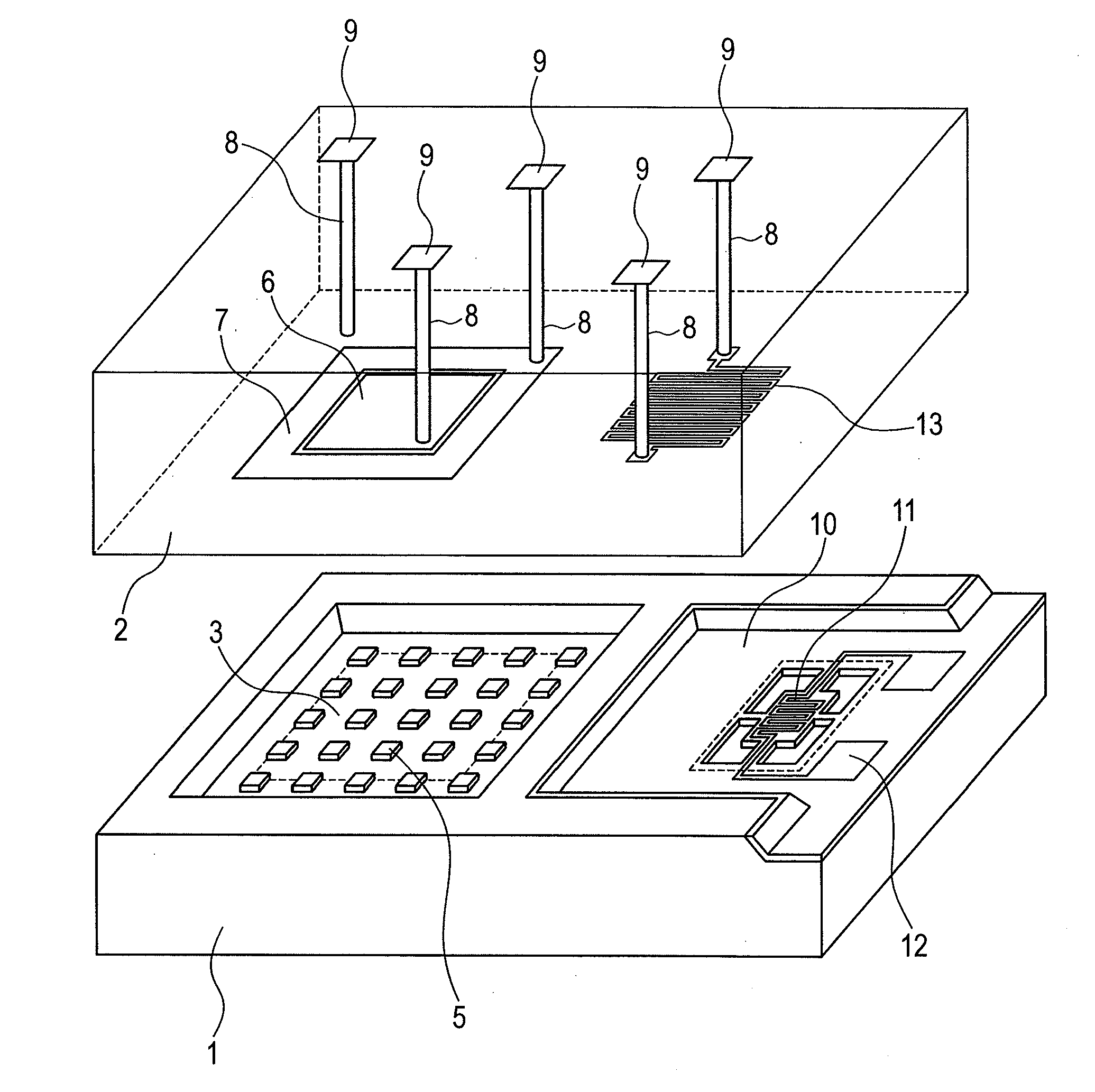
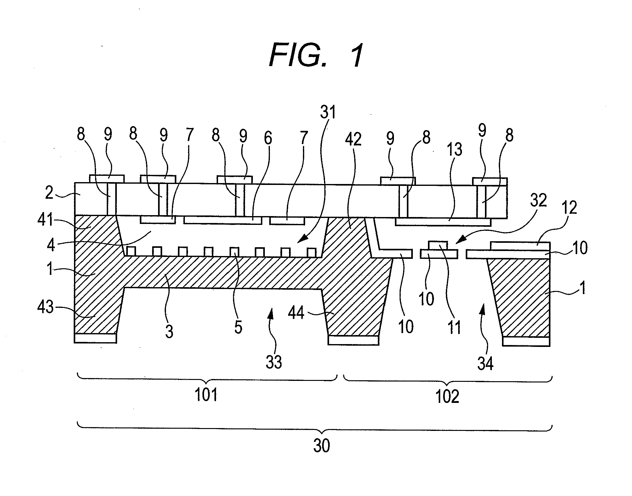
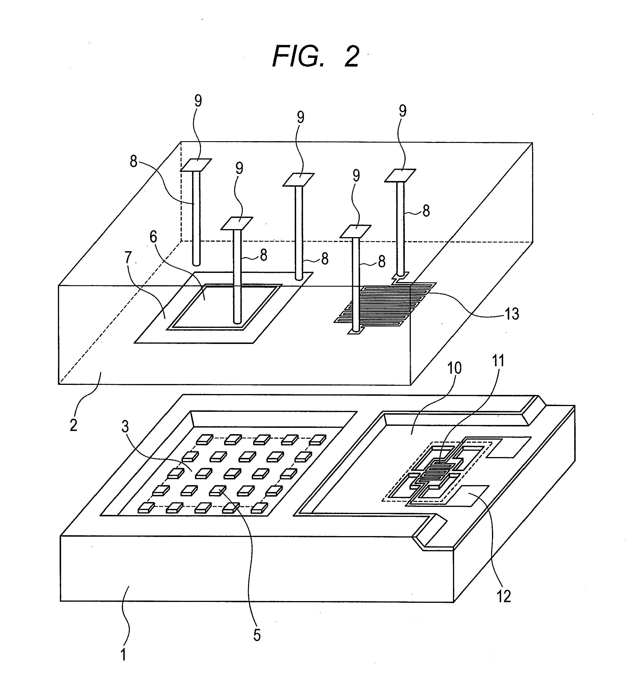
[0018]In recent years, the advance of a micromachine (Microelectro Mechanical Systems: MEMS) technology has enabled manufacturing of fine mechanical structures in a large amount with a low cost. The technology is also applied to the manufacturing technology of pressure gauges, and the capacitive pressure gauge and the Pirani pressure gauge may also be manufactured by a micromachine technology. An embodiment of the present invention is the manufacturing method of a combined type pressure gauge in which a single substrate is processed to give a combined type pressure gauge by a manufacturing process using the MEMS technology, instead of manufacturing separately both pressure gauges to assemble them as one combined type pressure gauge. That is, an embodiment of the present invention is the manufacturing method of a combined type pressure gauge in which the manufacturing process of both pressure gauges is made common to enable the combined type pressure gauge to be manufactured efficien...


PUM

PropertyMeasurementUnit
pressureaaaaaaaaaa
thicknessaaaaaaaaaa
gas pressureaaaaaaaaaa

Abstract

The present invention allows manufacturing of a capacitive diaphragm pressure gauge and a Pirani pressure gauge on a single silicon substrate, which makes it possible to reduce the manufacturing cost by the miniaturization of products and mass production. According to an embodiment of the present invention, the manufacturing method of a combined type pressure gauge is a manufacturing method of a combined type pressure gauge including a capacitive diaphragm pressure gauge and a Pirani pressure gauge, the method including a groove-forming step of forming a first groove portion and a second groove portion on a first surface side of a silicon substrate by etching, and a bonding step to bond a glass substrate to the silicon substrate so as to cover the first groove portion and the second groove portion on the first surface side of the silicon substrate.

Description

CROSS-REFERENCES TO RELATED APPLICATIONS[0001]This application claims the benefit of priority from Japanese Patent Application No. 2010-041197 filed Feb. 26, 2010, the entire contents of which is incorporated herein by reference.BACKGROUND OF THE INVENTION[0002]1. Field of the Invention[0003]The present invention relates to a combined type pressure gauge, and the manufacturing method of the combined type pressure gauge.[0004]2. Description of the Related Art[0005]In the pressure gauge described in Japanese Unexamined Patent Application Publication (Translation of PCT Application) No. 2002-520613, a protective tube having a flange for being connected to a vacuum apparatus etc. and a supporting plate are welded via an elastic spring. To the supporting plate, a diaphragm made of ceramic is arranged via a glass seal tube, and the space surrounded by these forms a reference vacuum chamber. Here, when gas pressure is applied to the diaphragm from the outside, the diaphragm is deflected to...

Claims


Application Information

Patent Timeline
Patent Type & Authority Applications(United States)
IPC IPC(8): G01L21/12G01L9/12B32B37/02
CPCG01L9/0073Y10T156/1064G01L21/12
Inventor MIYASHITA, HARUZO
Owner CANON ANELVA CORP
Why Eureka
Try Eureka