Adaptive imaging using digital light processing

a technology of light processing and adaptive imaging, applied in the field of adaptive imaging using digital light processing, can solve the problems of poor image quality, increased cost, and end up being too dark and noisy in the dark areas, and achieve the effect of reducing costs

Active Publication Date: 2011-09-01
THE TRUSTEES OF COLUMBIA UNIV IN THE CITY OF NEW YORK
View PDF15 Cites 105 Cited by
  • Summary
  • Abstract
  • Description
  • Claims
  • Application Information

AI Technical Summary

Benefits of technology

[0015]Another object of the present invention is to provide techniques for digitally capturing and processing high dynamic range still and video images of a scene at reduced costs.
[0016]A further object of the present invention is to provide techniques capable of adaptively capturing and processing high dynamic range still and video images of a scene, regardless of the dynamic range of the image sensor employed.
[0017]Yet another object of the present invention is to provide techniques capable of adaptively capturing and processing high dynamic range still and video images of a scene using feedback from an image sensor to optimize such image capture and processing.

Problems solved by technology

As a typical image capture device, such as a charge-coupled device (“CCD”) operates with eight bits of resolution, only 256 luminance values are available to span the entire brightness spectrum in such circumstances, and often yield a poor images.
While higher dynamic range image sensors, such as sixteen bit CCDs, are commercially available, they come at an increased cost which may be undesirable, and regardless of scene brightness operate within a fixed dynamic range.
In contrast, a low exposure image will have less saturation in bright regions but end up being too dark and noisy in the dark areas.
Unfortunately, sequential exposure change techniques are inherently suited only to static scenes, and the imaging system, scene objects and their respective radiance levels must remain constant during the sequential capture of images under different exposures.
While this approach is capable of producing high dynamic range images in real time, with both scene objects and the imaging system free to move during the capture process, a disadvantage is that this approach is expensive as it requires multiple image detectors, precision optics for the alignment of all the acquired images and additional hardware for the capture and processing of multiple images.
However, this technique is also expensive as it requires a sophisticated detector to be fabricated.
This approach faces the challenge of scaling to high resolution while keeping fabrication costs under control.
In addition, since exposure times can be large in dark scene regions, the method is expected to be more susceptible to motion blur.
Unfortunately, a trade-off of spatial resolution of an image is made in order to improve brightness resolution, or dynamic range.
Moreover, the fixed pixel exposure values do not provide the ability to measure each image brightness with the best precision possible.

Method used


Image

  • Adaptive imaging using digital light processing
  • Adaptive imaging using digital light processing
  • Adaptive imaging using digital light processing

Examples


embodiment 300

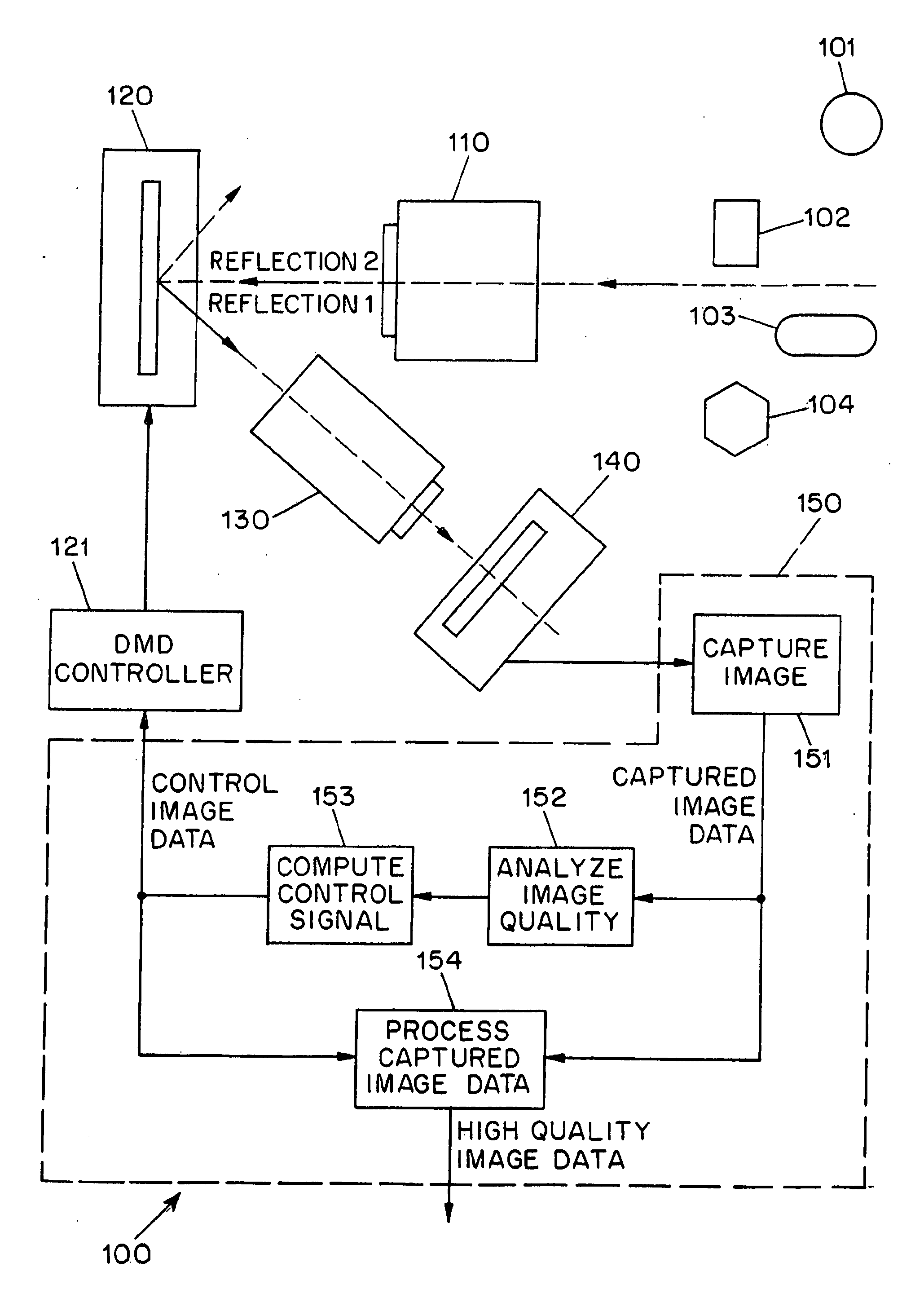
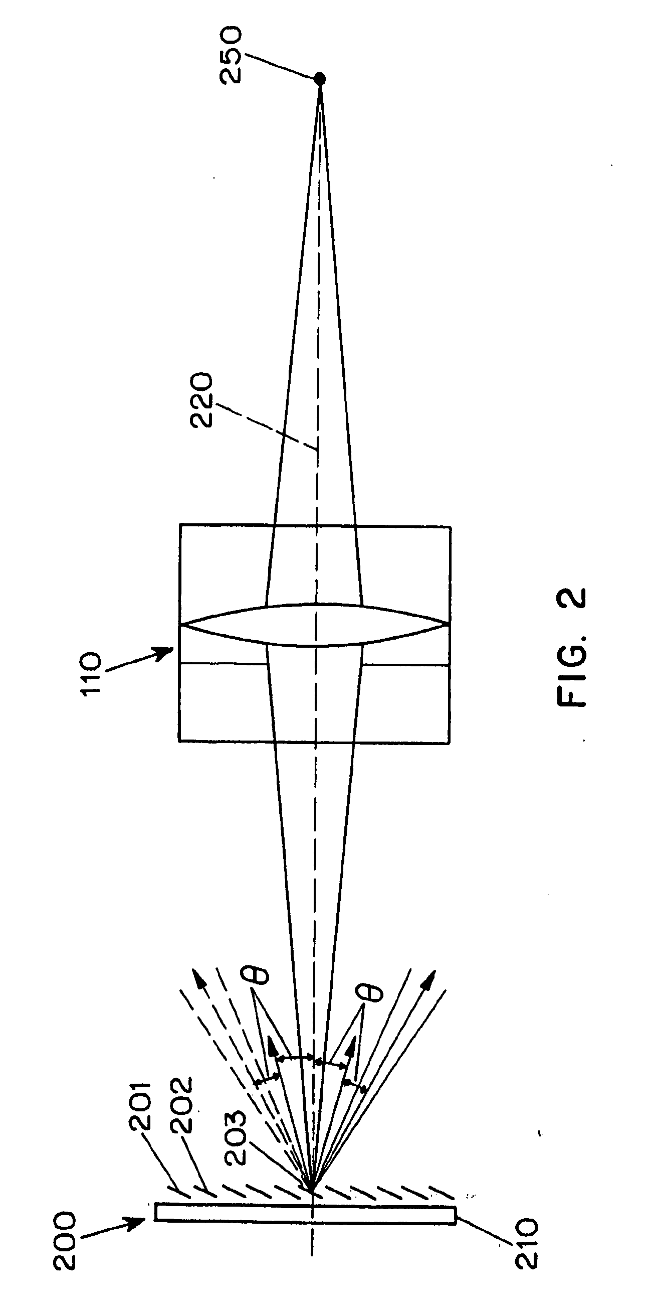
[0054]Referring next to FIG. 3, an embodiment 300 suitable for low resolution spatial image modulation will be explained. When a DMD is placed in front of an image, it can be used to modulate the imaged light rays. In this case, given a finite imaging aperture, a neighborhood of micromirrors 301, 302, 303 (rather than a single one) modulate the radiance of a scene point before it is imaged by a pixel 312 on the detector 140. Therefore, the irradiance of the pixel can be controlled by controlling a set of micromirrors, rather than a single one. In this case, the effective modulation function ends up being smooth or blurred, and the irradiance at any given pixel 311 cannot be controlled without effecting the irradiances of neighboring pixels.

[0055]In many applications smooth modulation functions will suffice and hence this configuration is a useful one. For instance, when the modulator is used to compensate for smoothly radiometric effects such as vignetting, low-resolution modulation...

embodiment 500

[0057]Referring next to FIG. 5, an preferred embodiment 500 suitable for high resolution spatial image modulation will be explained. In this embodiment, the scene is imaged onto the DMD 200, where the DMD plane is frontal, i.e., perpendicular to the optical axis of the imaging lens. When the micromirrors 501, 502, n, are located on a frontal plane, they are all oriented at one of the two possible tilt angles with respect to the plane. Each scene point is focused onto a single micromirror. For example, the light cone behind the lens 110 corresponding to a scene point 515 is reflected by the corresponding micromirror 505. Therefore, the micromirror serves as a virtual scene point that is located on the DMD plane. A relay lens 510 is then used to re-image the virtual scene point that is located on the DMD plane onto a single pixel on the image detector 140, e.g., the virtual scene point located on mircomirror 505 is re-imaged onto pixel 525. Since the light cones are reflected by the D...

embodiment 600

[0060]Referring next to FIG. 6, an embodiment 600 suitable for non-homogeneous image sensing will be explained. The embodiment is identical to that shown in FIG. 5, except that the image detector 140 is replaced by detector 610 adapted for a non-homogeneous pixel sensitivity to the various characteristics of light, e.g., color, spectrum brightness, or polarization. For example, a detector with a Bayer color mosaic may be used. Since the dynamic range of each pixel can controlled independently, the non-homogeneous nature of the detector is not an issue. The captured high quality data can be used to compute a high dynamic range color image.

[0061]Such non-homogeneous sensing is not restricted to color; the pixels may have different brightness sensitivities, e.g., as disclosed in S. K. Nayar et al., “High dynamic range imaging: Spatially varying Pixel exposures,”Proc. of Computer Vision and Pattern Recognition '00 (2000), the contents of which are incorporated by reference herein, or di...


PUM


Abstract

A system (100) for the adaptive imaging of a scene includes a digital light processing apparatus (150) adapted for controllably reflecting an image of the scene in at least a first direction to thereby reflect an intensity modulated image of the scene along at least the first direction, an image detector (140) for detecting the intensity modulated image of the scene and generating corresponding image data, and an image data processor (154) for processing the image data into control data and providing the control data to the digital light processing (150) apparatus for control thereof.

Description

CROSS-REFERENCE TO RELATED APPLICATIONS[0001]This application is based on U.S. provisional patent application Ser. No. 60 / 311,158 filed Aug. 9, 2001, which is incorporated herein by reference for all purposes and from which priority is claimed.BACKGROUND OF THE INVENTION[0002]1. Technical Field[0003]The present invention relates to techniques for digitally capturing and processing high dynamic range still and video images of a scene using relatively low resolution image detectors, and more particularly, to techniques capable of adaptively capturing and processing such images.[0004]2. Background Art[0005]In digital photography and video imaging, it is often necessary to capture images of a scene which includes areas of greatly disparate luminance. An extreme example lies in the imaging of a solar eclipse, where a nearly black object, the moon, is directly adjacent an extraordinarily bright object, the sun. Other more common examples include photographing a person with the sun in the ...

Claims


Application Information

Patent Timeline
Patent Type & Authority Applications(United States)
IPC IPC(8): H04N5/225H04N5/222G02B26/06H04N5/235H04N5/238
CPCG02B26/06H04N5/238H04N5/2355H04N5/235H04N23/70H04N23/741H04N23/75G02B26/0833H04N25/63H04N25/61
Inventor NAYAR, SHREE K.BOULT, TERRANCE E.
Owner THE TRUSTEES OF COLUMBIA UNIV IN THE CITY OF NEW YORK
Why Eureka
Try Eureka