Turbine airfoil having outboard and inboard sections

a technology of turbine airfoils and turbines, which is applied in the direction of liquid fuel engines, vessel construction, marine propulsion, etc., can solve the problems of large root size and the possibility of failur

Inactive Publication Date: 2011-09-08
SIEMENS ENERGY INC
View PDF8 Cites 12 Cited by
  • Summary
  • Abstract
  • Description
  • Claims
  • Application Information

AI Technical Summary

Benefits of technology

[0006]This invention relates to a turbine airfoil formed from an inboard section and an outboard section attached thereto. The outboard section may be configured with a tip having an appropriate size. The remaining portions of the outboard section may be generally the same as the tip. The inboard section may be configured to support the outboard section. Forming the outboard section in this manner enables turbine airfoils to be formed in larger sizes than conventional configurations without creating centrifugal loading problems during turbine engine operation. The configuration of the outboard section enables the airfoil wall to be thinner than conventional airfoil walls and enables the airfoil wall of the outboard section to be generally constant along the length of the outboard section to the inboard section, which may begin at a point where the airfoil begins to carry the centrifugal load.
[0008]An advantage of this invention is that by forming the airfoil from outboard and inboard sections, the sections may be individually cast, which allows the outboard and inboard sections to be thinner and thereby more efficient structurally than conventional airfoils.
[0009]Another advantage of this invention is that the outboard section may be formed from materials having a lower density than the inboard section, thereby increasing the structural efficiency of the airfoil by increasing the specific strength of the airfoil.
[0010]Yet another advantage of this invention is that the configuration of the outboard and inboard sections may reduce the centrifugal loads by more than 15 percent.
[0011]Another advantage of this invention is that the amount of stress in the outer walls forming the airfoils is reduced, thereby improving the overall structural efficiency of the airfoil.
[0012]Still another advantage of this invention is that the separately cast outboard section increases the structural efficiency in the critical outermost section of the airfoil and benefits the inboard section as it propagates radially inward through the airfoil.

Problems solved by technology

In addition, turbine vanes and blades often contain cooling systems for prolonging the life of the vanes and blades and reducing the likelihood of failure as a result of excessive temperatures.
While simply designing an appropriate tip thickness and increasing the tip thickness to the root is feasible for small turbine airfoils, such is not the case for large airfoils useful in large turbine engines.
In particular, when this design is scaled up to the larger engines, the root becomes larger than can be accommodated.
In addition, the larger sized airfoil requires a part span snubber or tip shroud for vibration control, both of which become very difficult with the large size and temperature.

Method used


Image

  • Turbine airfoil having outboard and inboard sections
  • Turbine airfoil having outboard and inboard sections
  • Turbine airfoil having outboard and inboard sections

Examples


Embodiment Construction

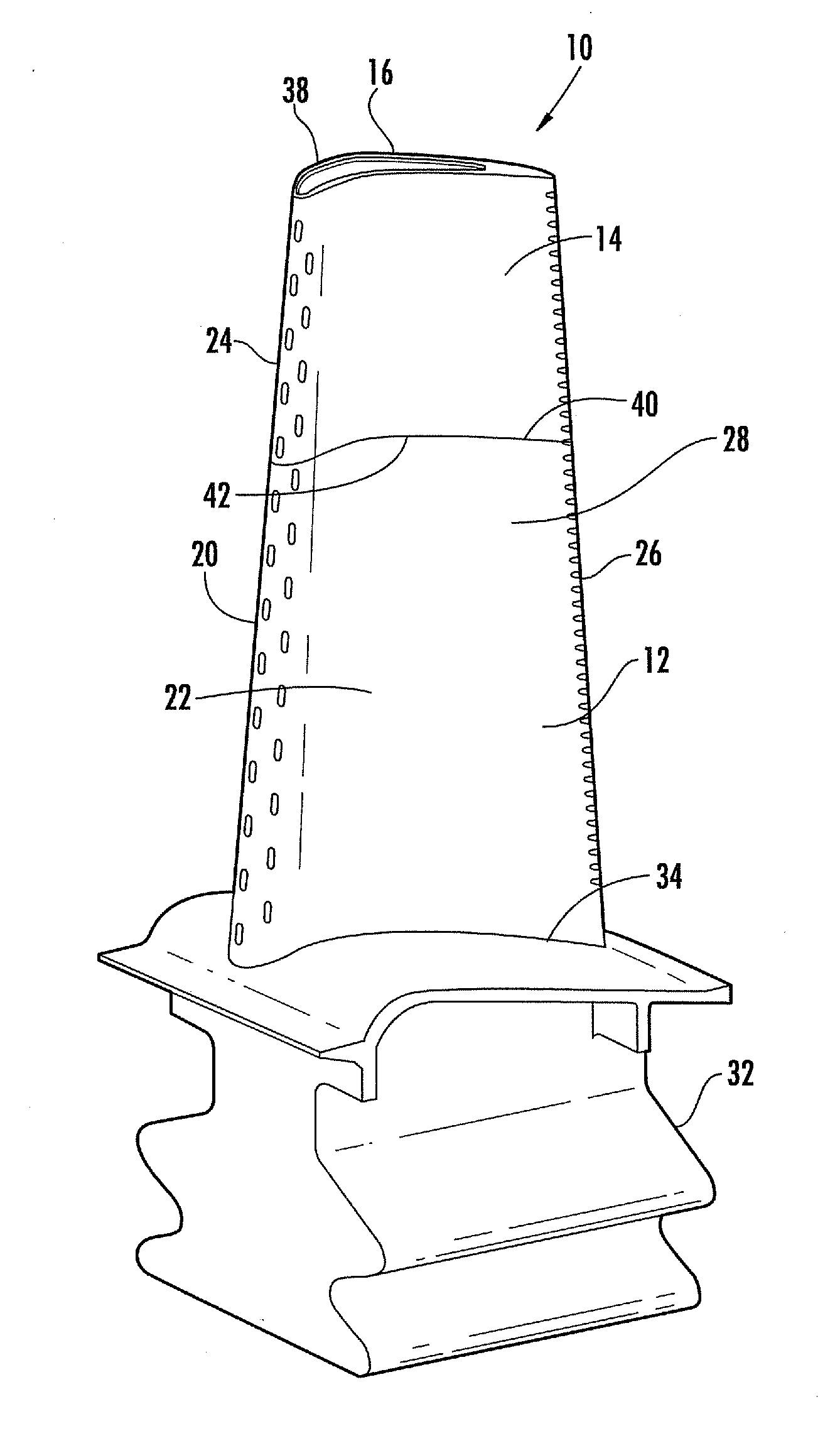
[0019]As shown in FIGS. 3-4, this invention is directed to a turbine airfoil 10 formed from an inboard section 12 and an outboard section 14 attached thereto. The outboard section 14 may be configured with a tip 16 having an appropriate size. The remaining portions of the outboard section 14 may be generally the same as the tip 16. The inboard section 12 may be configured to support the outboard section 14. Forming the outboard section 14 in this manner enables turbine airfoils 10 to be formed in larger sizes than conventional configurations without creating centrifugal loading problems during turbine engine operation. The configuration of the outboard section 14 enables the airfoil wall to be thinner than conventional airfoil walls and enables the airfoil wall of the outboard section 14 to be generally constant along the length of the outboard section 14 to the inboard section 12, which may begin at a point where the airfoil begins to require tapering walls to carry the increasing ...


PUM


Abstract

A turbine airfoil usable in a turbine engine and formed from at least an outboard section and an inboard section such that an inner end of the outboard section is attached to an outer end of the inboard section. The outboard section may be configured to provide a tip having adequate thickness and may extend radially inward from the tip with a generally constant cross-sectional area. The inboard section may be configured with a tapered cross-sectional area to support the outboard section.

Description

STATEMENT REGARDING FEDERALLY SPONSORED RESEARCH[0001]Development of this invention was supported in part by the United States Department of Energy, Contract No. DE-FC26-05NT42644, H2 Advanced Hydrogen Turbine Development, Phase 2. Accordingly, the United States Government may have certain rights in this invention.FIELD OF THE INVENTION[0002]This invention is directed generally to turbine airfoils, and more particularly to hollow turbine airfoils having cooling channels for passing fluids, such as air, to cool the airfoils.BACKGROUND[0003]Typically, gas turbine engines include a compressor for compressing air, a combustor for mixing the compressed air with fuel and igniting the mixture, and a turbine blade assembly for producing power. Combustors often operate at high temperatures that may exceed 2,500 degrees Fahrenheit. Typical turbine combustor configurations expose turbine vane and blade assemblies to these high temperatures. As a result, turbine vanes and blades must be made of...

Claims


Application Information

Patent Timeline
Patent Type & Authority Applications(United States)
IPC IPC(8): F01D5/14
CPCF01D5/14F01D5/147F01D5/28
Inventor MAZZOLA, STEFANMARRA, JOHN J.
Owner SIEMENS ENERGY INC
Why Eureka
Try Eureka