Network Interface Apparatus

a network interface and apparatus technology, applied in the direction of data switching details, instruments, sustainable buildings, etc., can solve the problems of limited unnecessary activation of the second communication control unit, low frequency of operation clock, and relatively slow processing speed, so as to reduce power consumption

Active Publication Date: 2011-09-08
MURATA MASCH LTD
View PDF3 Cites 12 Cited by
  • Summary
  • Abstract
  • Description
  • Claims
  • Application Information

AI Technical Summary

Benefits of technology

In order to overcome the problems described above, a network interface apparatus is arranged to respond to requests from a network device at any time while reducing power consumption.

Problems solved by technology

Accordingly, such unnecessary activation of the second communication control unit is limited so as to reduce power consumption of the network interface apparatus.
Furthermore, a CPU with a low frequency of operation clock and a relatively slow processing speed can be used.

Method used


Image

  • Network Interface Apparatus
  • Network Interface Apparatus
  • Network Interface Apparatus

Examples


Embodiment Construction

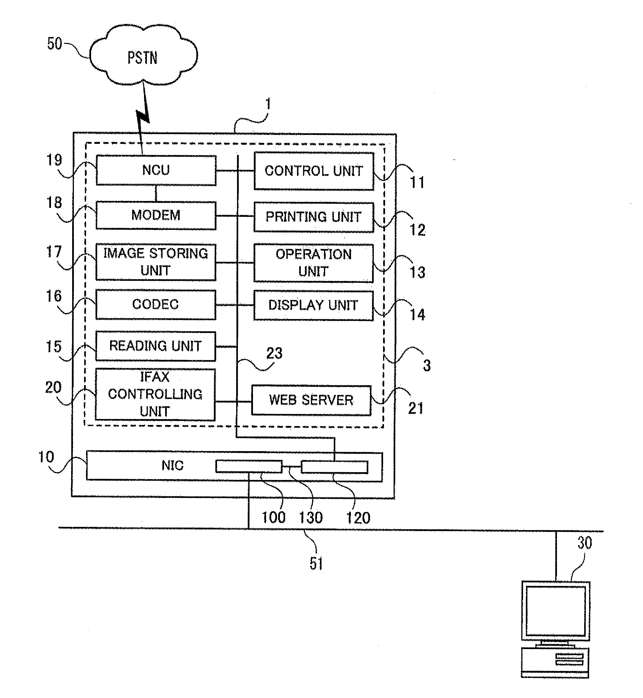
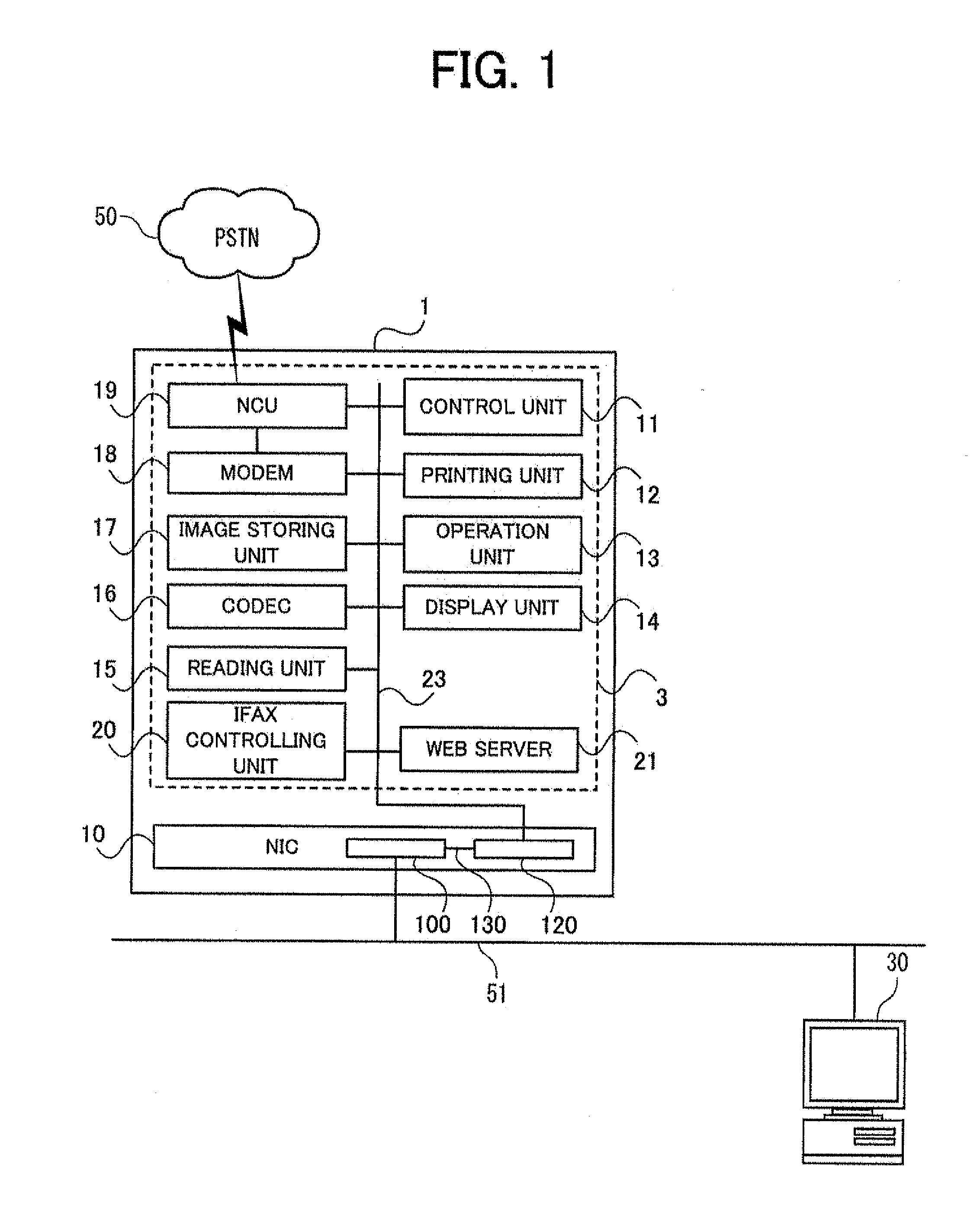
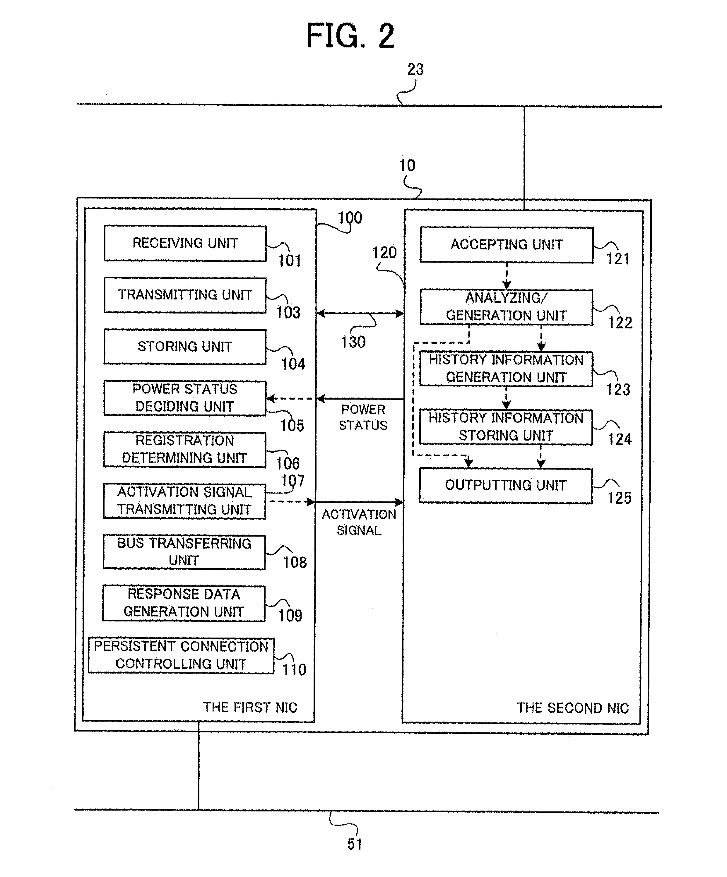
Preferred embodiments are now described with reference to the drawings. In the drawing figures, like reference numerals refer to like parts, unless otherwise indicated. An MFP (Multi Function Peripheral) equipped with a network interface apparatus according to an embodiment, i.e. a network MFP, is described as an example. Further, a network system in which a network MFP is connected to a personal computer as a network device via a LAN is described as an example. The network system illustrated as an example is simplified to facilitate understanding of the configuration. Now, with reference to FIG. 1 and FIG. 2, the configuration of a network MFP 1 and a network interface controller (network interface apparatus, hereinafter: NIC) 10 is described. FIG. 1 is a block diagram illustrating an entire configuration of the network MFP 1 connected to a LAN 51. FIG. 2 is a block diagram illustrating the configuration of the NIC 10.

The network MFP 1 has an energy saving status while waiting, and...


PUM


Abstract

A network interface controller includes a first NIC connected to a LAN and a second NIC, which can proceed to a low power consumption status, connected to the first NIC via a bus. The first NIC includes a storing unit arranged to store response history information transmitted from the second NIC, a registration determining unit arranged to determine whether the received data has been registered in the response history information when network data is received and the status of the second NIC is the low power consumption status, a transmitting unit arranged to transmit response data registered in association with the received data when the received data has been registered, and an activation signal transmitting unit arranged to transmit an activation signal to the second NIC when the received data has not been registered.

Description

CROSS-REFERENCE TO RELATED APPLICATIONSThis application claims priority under 35 U.S.C. 119 to Japanese Patent Application No. 2010-049105, filed on Mar. 5, 2010, which application is hereby incorporated by reference in its entirety.BACKGROUND OF THE INVENTION1. Field of the InventionThe present invention relates to a network interface apparatus arranged to communicate via a network.2. Description of the Related ArtIn recent years, in view of issues such as reduction of CO2 emission, lowering power consumption of electric devices has been socially demanded. For example, in a network device connected to a network such as a LAN, the network device saves power by turning off the power of a CPU or a hard disc and operating only a network interface controller (NIC) that is directly connected to the network.In such a network device, an information processing device saves power without interfering with a low power consumption mode of units other than a network interface unit even when a st...

Claims


Application Information

Patent Timeline
Patent Type & Authority Applications(United States)
IPC IPC(8): G06F1/00
CPCG06F1/00Y02B60/1235Y02B60/1228Y02D10/00H04L12/12G06F1/3209H04L41/0213
Inventor KUWAHARA, TETSUYA
Owner MURATA MASCH LTD
Why Eureka
Try Eureka