Light-emitting device

a light-emitting device and light-emitting technology, which is applied in the manufacture of semiconductor/solid-state devices, semiconductor devices, electrical devices, etc., can solve the problems of deteriorating light intensity, inadequate emission brightness, and increasing heat generation, and achieve excellent light extraction efficiency, high heat dissipation property, and high light reflection efficiency.

Active Publication Date: 2011-09-15
ASAHI GLASS CO LTD
View PDF7 Cites 27 Cited by
  • Summary
  • Abstract
  • Description
  • Claims
  • Application Information

AI Technical Summary

Benefits of technology

[0025]According to the present invention, it is possible to provide a light-emitting device mounting a light-emitting element having a reflective metal film on the surface on the side opposite to a light emitting layer, which is excellent in light extraction efficiency as it has high heat dissipation property and high light reflection efficiency, and which can suppress deterioration of the light extraction efficiency due to the deterioration with time.

Problems solved by technology

However, in such a light-emitting device, there has been a problem such that along with a tendency to high brightness of a LED element, heat generation is also increasing, and the temperature increases excessively, whereby adequate emission brightness has not necessarily been obtained.
Further, in order to obtain a high light extraction efficiency, a technology has been proposed to dispose a silver reflection film on e.g. a substrate surface to mount a LED element, but in such a light-emitting device, there has been a problem of so-called light intensity deterioration such that the light extraction efficiency deteriorates as compared with the initial stage since a silver reflection film is deteriorated by oxidation or sulfurization due to heat or permeated gas.
Further, in such a light-emitting device using a conventional LED element, in consideration of the heat dissipation property, an electroconductive die bond material made of a thermosetting resin containing e.g. silver particles is preferred as a die bond material, but the electroconductive die bond material is not usually used since the light extraction efficiency tends to deteriorate due to low reflectance of the electroconductive die bond material.
Accordingly, the light extraction efficiency is insufficient, and it is impossible to obtain light having high brightness corresponding to high output of the light-emitting element.

Method used


Image

  • Light-emitting device
  • Light-emitting device
  • Light-emitting device

Examples


example 1

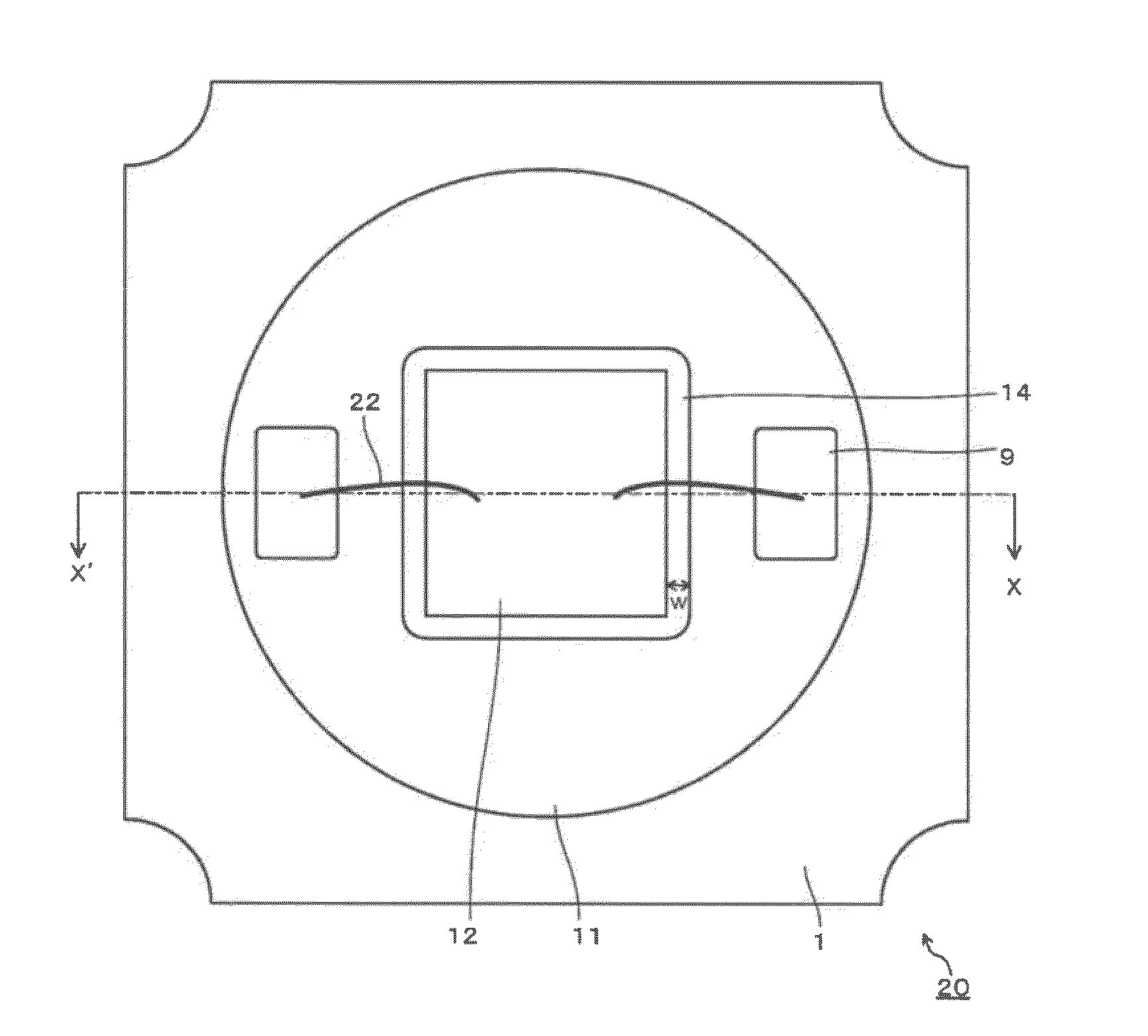
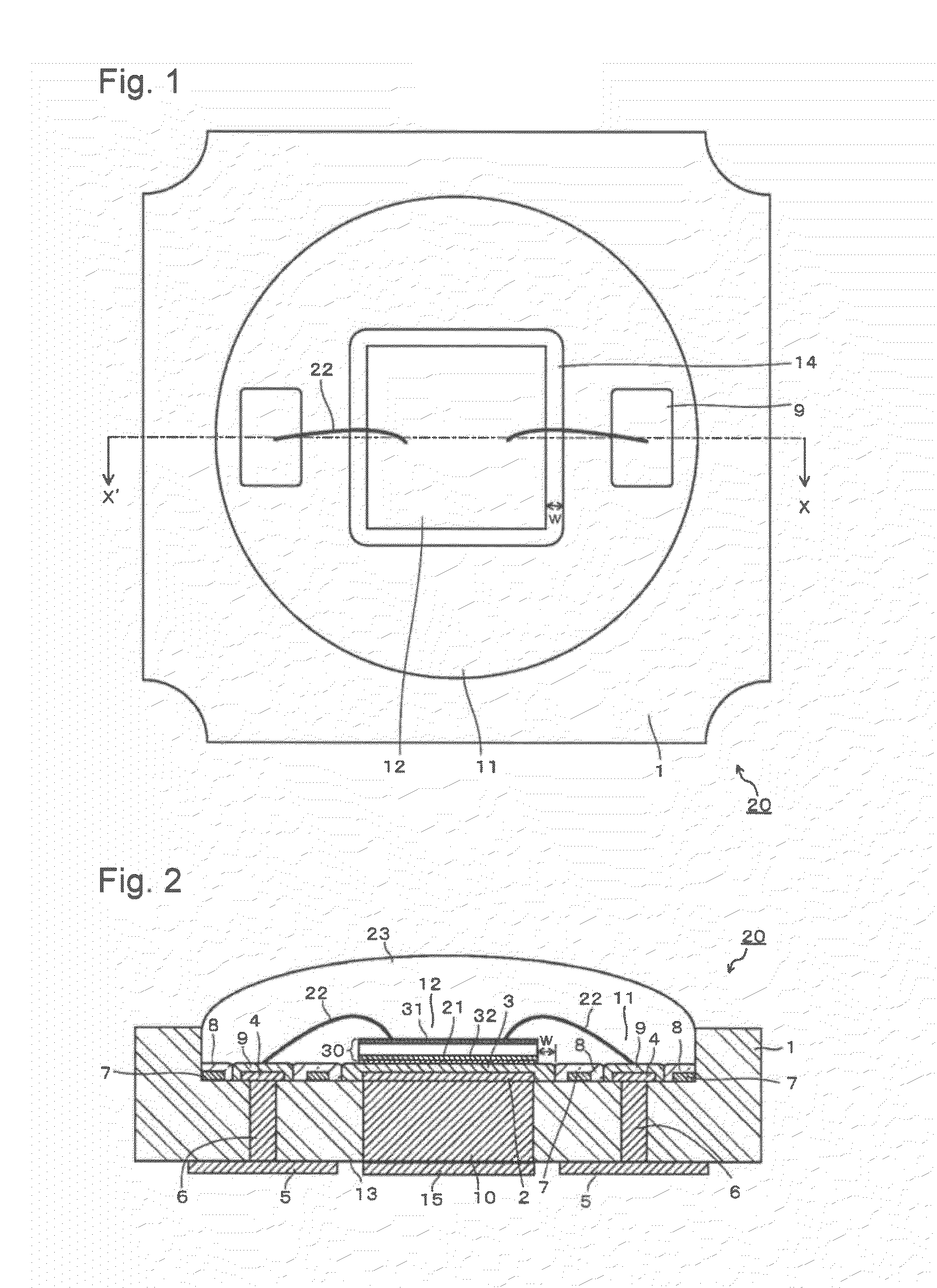
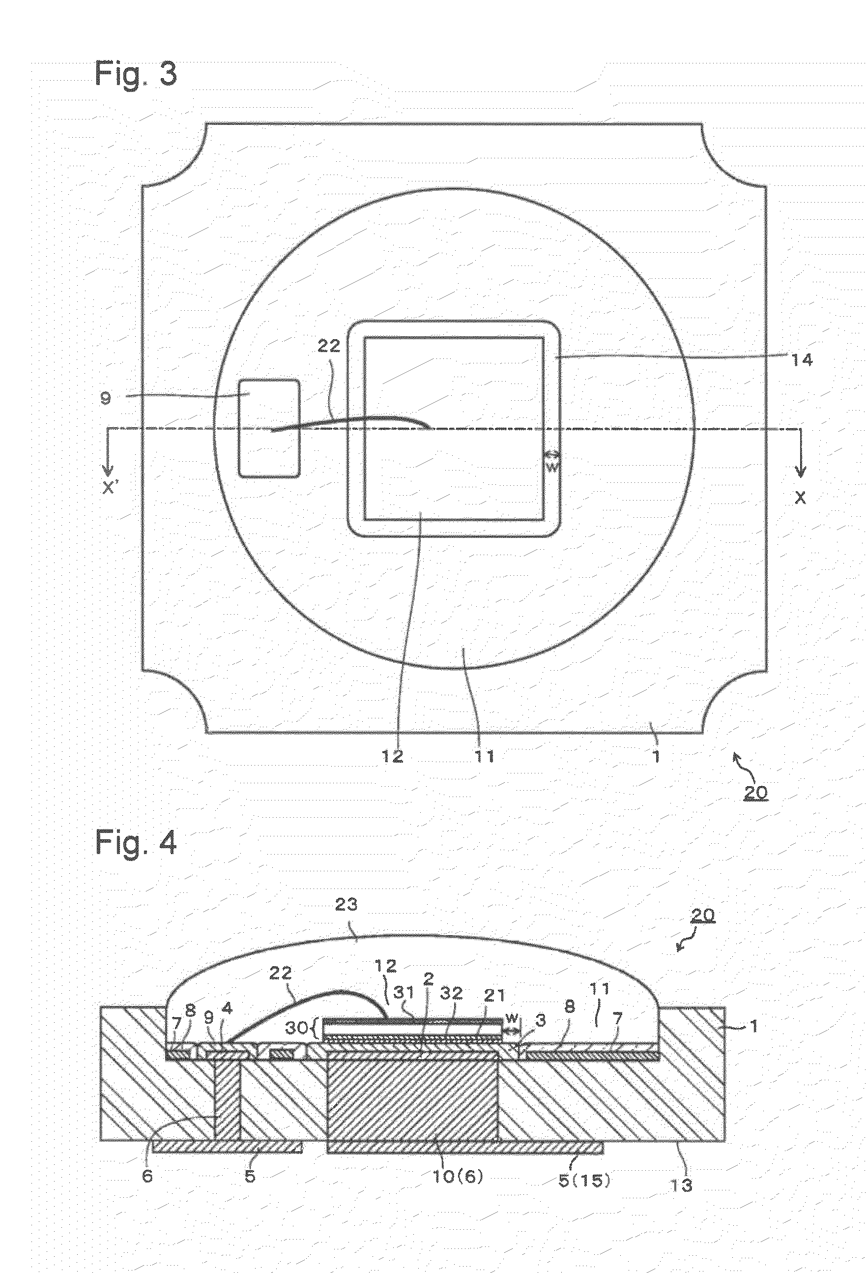
[0137]By the following process, a light-emitting device for test, employing a LTCC substrate having the same structure as in FIGS. 1 and 2 was prepared. Here, in the same manner as above, the same symbols are used for the components before and after the firing.

[0138]Firstly, a main body green sheet 1 was prepared to prepare the main body LTCC substrate 1 of a substrate for mounting light-emitting element. For the main body green sheet 1, raw materials were blended and mixed so that SiO2 became 60.4 mol %, B2O3 15.6 mol %, Al2O3 6 mol %, CaO 15 mol %, K2O 1 mol % and Na2O 2 mol %, and this raw material mixture was put into a platinum crucible and melted at 1,600° C. for 60 minutes. Then, this molten state glass was cast and cooled. This glass was ground by a ball mill made of alumina for 40 hours to obtain a glass powder for substrate main body. Here, ethyl alcohol was used as the solvent at the time of grinding.

[0139]40 mass % of this glass powder for substrate main body and 60 mass...

example 2

[0150]A light-emitting device was prepared in the same manner as in Example 1 except that by using the same glass powder as in Example 1, 38 mass % of this glass powder, 38 mass % of alumina filler (tradename: AL-45H manufactured by Showa Denko K.K.) and 24 mass % of zirconia filler (tradename: HSY-3F-J manufactured by Daiichi Kigenso Kagaku Kogyo Co., Ltd.) were blended and mixture to prepare a glass ceramics composition.


PUM


Abstract

To provide a light-emitting device mounting a light-emitting element having a metal film on the rear side surface, which is excellent in light extraction efficiency since it has high heat dissipating properties and high light reflection efficiency, and which can suppress the reduction of light extraction efficiency due to the deterioration with time.
A light-emitting device which comprises:
    • a substrate made of an inorganic insulating material,
    • a metal conductor layer formed on the mounting portion of the substrate,
    • a conductive protective layer formed on the above metal conductor layer,
    • a light-emitting element having a metal film on the rear side surface, and mounted on the mounting portion of the above substrate so that the metal film faces the conductive protective layer and is located inside the edge of the conductive protective layer,
    • an electroconductive bonding material to bond the light-emitting element with the conductive protective layer,
    • a reflection film formed on the mounting surface of the above substrate in such a shape as to exclude the conductive protective layer and the vicinity around it, and
    • an insulating protective layer formed on the mounting surface of the substrate so as to cover the entirety of the above reflection film including its edge.

Description

TECHNICAL FIELD[0001]The present invention relates to a light-emitting device. More particularly, it relates to a light-emitting device mounting a high-output light-emitting element, and having high brightness and less deterioration of light intensity.BACKGROUND ART[0002]In recent years, along with a tendency to high brightness and whitening of a light-emitting diode (LED) element, a light-emitting device employing a LED element has been used for backlights of mobile phones, liquid crystal TVs, liquid crystal displays, etc.[0003]However, in such a light-emitting device, there has been a problem such that along with a tendency to high brightness of a LED element, heat generation is also increasing, and the temperature increases excessively, whereby adequate emission brightness has not necessarily been obtained. Further, in order to obtain a high light extraction efficiency, a technology has been proposed to dispose a silver reflection film on e.g. a substrate surface to mount a LED e...

Claims


Application Information

Patent Timeline
Patent Type & Authority Applications(United States)
IPC IPC(8): H01L33/46
CPCH01L33/44H01L33/46H01L33/486H01L33/60H01L2224/32225H01L2224/48091H01L2224/48227H01L2224/73265H01L2924/00014H01L2924/00H01L2924/181
Inventor NAKAYAMA, KATSUYOSHI
Owner ASAHI GLASS CO LTD
Why Eureka
Try Eureka