Wide Range Current Sensing

Active Publication Date: 2011-09-15
APPLE INC
View PDF5 Cites 15 Cited by
  • Summary
  • Abstract
  • Description
  • Claims
  • Application Information

AI Technical Summary

Benefits of technology

[0010]This provides a current sense configuration with the capability of measuring load currents within a wide dynamic range, while providing fine granularity when measuring low (e.g. under 100 mA) currents. The current sense circuit may also incorporate a voltage control circuit for directly setting the value of the voltage at the supply terminal of the DUT device by providing a feedback voltage to the voltage regulator. The voltage control circuit may include a capacitor for readjusting the phase margin and thus provide a better loop response during voltage regulation.
[0011]Current conducted by a load may therefore be sensed and/or measured by establishing a first current flowing through a first current path into a power terminal of the load, and respons

Problems solved by technology

For example, the low-side resistor adds undesirable extraneous resistance in the ground path, while circuitry associated with the high-side resistor has to withstand relatively large common-mode signals.
Disadvantages of low-side current sensing include the load being lifted from direct ground connection.
Disadvantages of high-side current sensing include high input common-mode voltages, and the need t

Method used


Image

  • Wide Range Current Sensing
  • Wide Range Current Sensing
  • Wide Range Current Sensing

Examples


Embodiment Construction

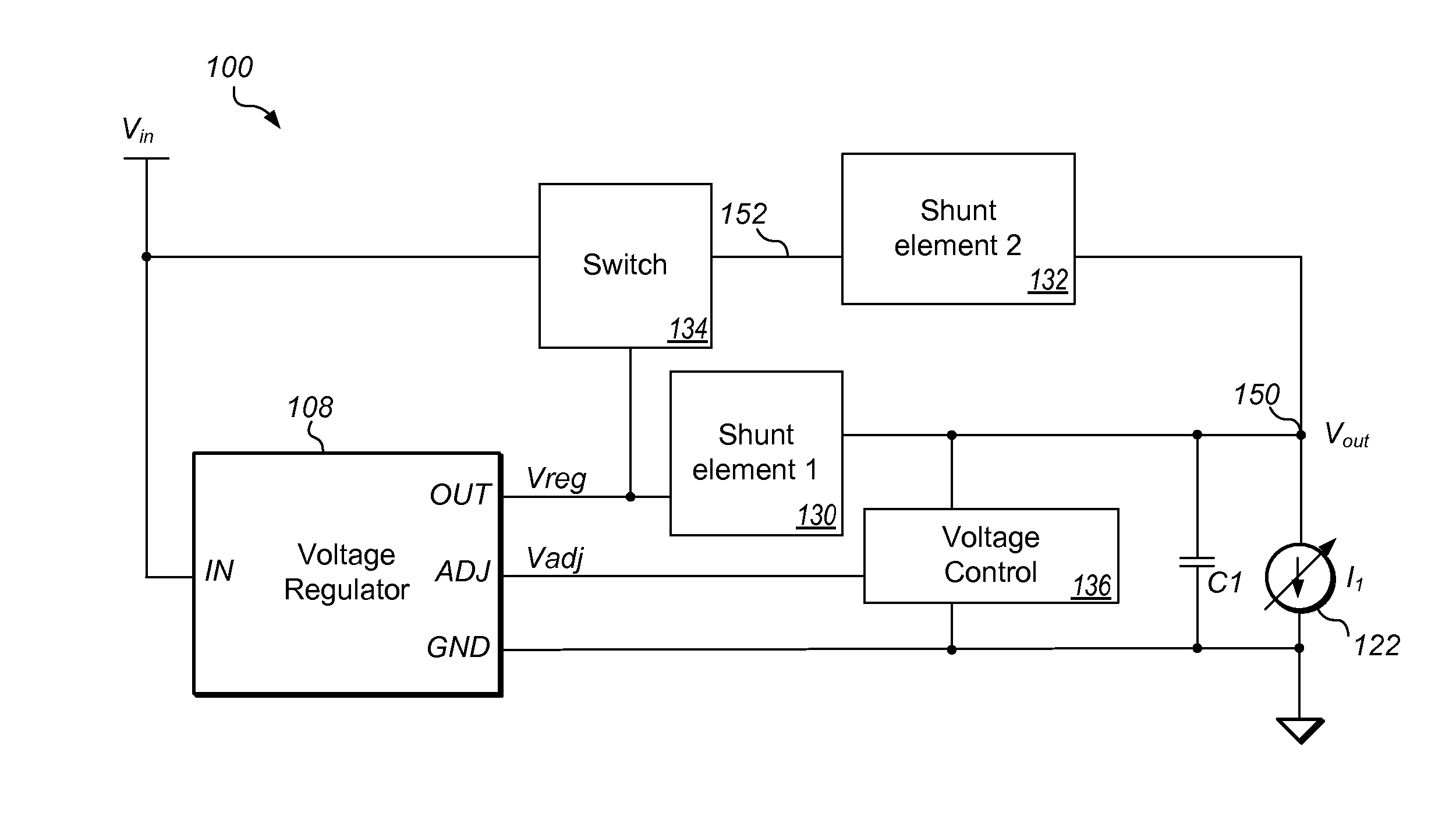
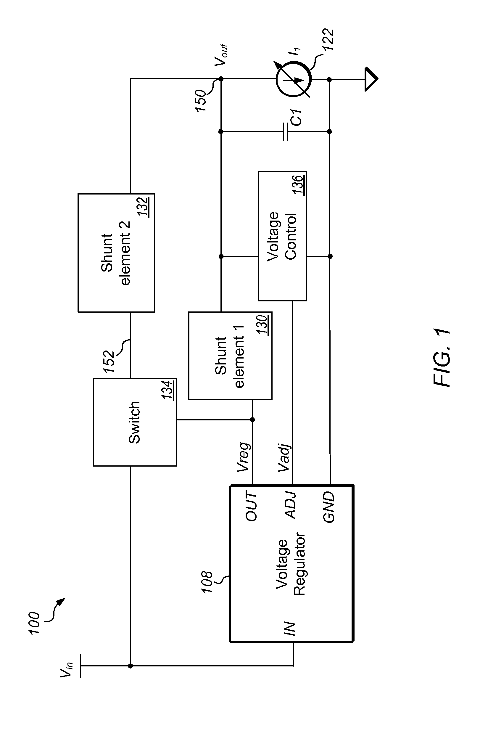
[0018]FIG. 1 shows a current sense circuit 100 for measuring current conducted by a device under test (DUT) 122, according to one set of embodiments. While load 122 is shown as being coupled to the current sense circuit, load 122 is not functionally a part of current sense circuit 100, but is rather any device / load that may be coupled to current sense circuit 100 for the purpose of measuring the current conducted by load 122. As shown in FIG. 1, current sense circuit 100 may be built around a voltage regulator 108, which may be a linear low-dropout (LDO) voltage regulator, configured to receive an input voltage Vin at an input terminal and provide a regulated output voltage Vreg based on Vin. As also shown in FIG. 1, a first current branch may be established from the output terminal of voltage regulator 108 through a first shunt element 130 to the supply terminal (at node 150) of the load device (or DUT) 122. A second current branch may also be established, in parallel with the firs...


PUM


Abstract

A current sense circuit, including a voltage regulator, for detecting current conducted by a device under test (DUT) for a wide range of currents, while still providing fine granularity for detecting low/small currents. Two current branches/paths may be established to the supply terminal of the DUT. A switching device, e.g. a transistor device, may be operated to enable a first current branch of the two current branches, or both current branches to conduct current, responsive to the size of the current flowing in the first current branch. The total current conducted by the DUT may be equivalent to a sum of the respective currents flowing in the two current branches.
When the switching device is turned off, very small currents conducted by the DUT may be measured with fine granularity. When the switching device is turned on, substantially larger currents conducted by the DUT may be measured.

Description

BACKGROUND[0001]1. Field of the Invention[0002]This invention is related to the field of electrical measurements, more particularly, to current sensing.[0003]2. Description of the Related Art[0004]Measuring, sensing and / or controlling current flow into and out of electronic circuits is an important requirement in many electronic systems, spanning a wide range of applications. There are numerous different current sensing techniques, which are as diverse as the applications that require monitoring current flow. Examples of systems that may rely on current sensing to perform essential functions include programmable current sources, overcurrent-protection and monitoring devices, various low-current systems, battery chargers, various power supplies, and circuits where the ratio of output current to input current is of importance. In addition, portable applications may also require dedicated current monitors that fit in a small package and operate with low quiescent current.[0005]The two ...

Claims


Application Information

Patent Timeline
IPC IPC(8): G01R1/20
CPCG01R19/0092G01R1/203
Inventor MCNAMARA, ROBERT
Owner APPLE INC
Why Eureka
Try Eureka