X-ray inspection apparatus and x-ray inspection method

a technology of x-ray inspection and x-ray, applied in the direction of material analysis using wave/particle radiation, instruments, nuclear engineering, etc., can solve the problem that poor locations cannot be observed with visible-light optical means such as microscopes, and achieve the effect of lowering inspection efficiency and lowering inspection efficiency

Inactive Publication Date: 2011-09-15
ORMON CORP
View PDF4 Cites 11 Cited by
  • Summary
  • Abstract
  • Description
  • Claims
  • Application Information

AI Technical Summary

Benefits of technology

[0009]One or more embodiments of the present invention provide an X-ray inspection apparatus that enables detailed analysis to be performed without lowering inspection efficiency.
[0010]One or more embodiments of the present invention provide an X-ray inspection method that enables detailed analysis to be performed without lowering inspection efficiency.

Problems solved by technology

However, in the case where the solder connections of a BGA (Ball Grid Array), a CSP (Chip Size Package) or the like, which cannot be optically inspected with visible light from the exterior, are automatically inspected by an X-ray inspection apparatus, locations that have been determined as being poor cannot be observed with a visible-light optical means such as a microscope.

Method used


Image

  • X-ray inspection apparatus and x-ray inspection method
  • X-ray inspection apparatus and x-ray inspection method
  • X-ray inspection apparatus and x-ray inspection method

Examples


first embodiment

Overview of Configuration

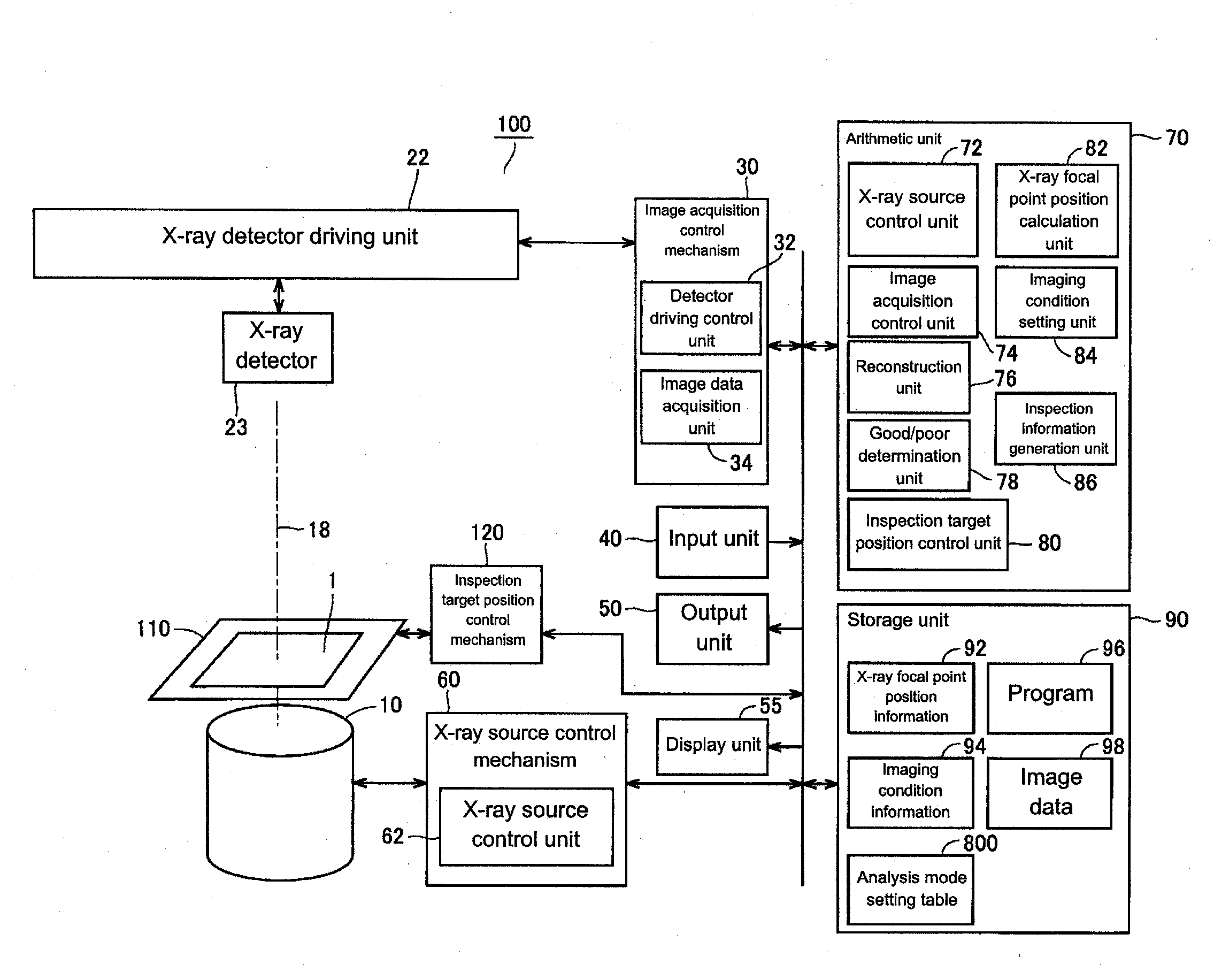
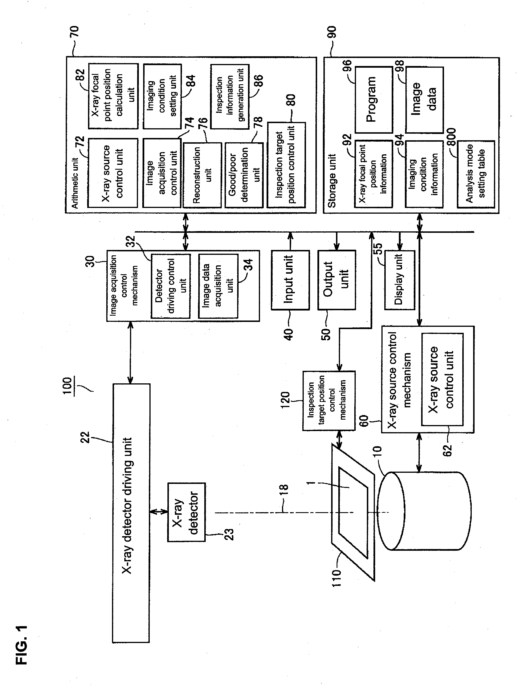
[0046]Below is a description of the configuration of an X-ray inspection apparatus 100 according to a first embodiment with reference to FIG. 1. FIG. 1 is a schematic block diagram of the X-ray inspection apparatus 100 according to the present embodiment.

[0047]The X-ray inspection apparatus 100 includes an X-ray source 10 that outputs X-rays 18, an X-ray detector 23, an image acquisition control mechanism 30, and an inspection target position driving mechanism 110 that moves the position of an inspection target 1. The X-ray inspection apparatus 100 further includes an input unit 40, an output unit 50, a display unit 55, an X-ray source control mechanism 60, an inspection target position control mechanism 120, an arithmetic unit 70, and a storage unit 90.

[0048]The inspection target 1 is arranged between the X-ray source 10 and the X-ray detector 23. In the present embodiment, the inspection target 1 is assumed to be a circuit board on which a part is mounted....

second embodiment

Control Configuration

[0169]The following describes the control configuration of an X-ray inspection apparatus 100 according to a second embodiment with reference to FIG. 19. FIG. 19 is a flowchart showing processing performed using the X-ray inspection apparatus 100 according to the present embodiment. The inspection performed using the X-ray inspection apparatus according to the present embodiment differs from that using the X-ray inspection apparatus according to the first embodiment described above in that in the present embodiment, information regarding a board that has failed inspection is stored in a nonvolatile memory, and imaging and inspection for defect analysis are performed again after once again introducing the board. Note that the X-ray inspection apparatus 100 according to the present embodiment can be realized using the hardware for realizing the X-ray inspection apparatus 100 according to the first embodiment. Accordingly, a redundant description of the hardware wil...


PUM

PropertyMeasurementUnit
angleaaaaaaaaaa
angleaaaaaaaaaa
angleaaaaaaaaaa

Abstract

The X-ray inspection apparatus and method realize high-speed defect analysis inspection. The processing executed by the X-ray inspection apparatus includes executing high-speed imaging, creating an inspection image by executing reconstruction processing, and performing automatic inspection. If the object has passed automatic inspection, the processing executed by the X-ray inspection apparatus includes displaying inspection results. If the object has failed automatic inspection, the processing executed by the X-ray inspection apparatus includes switching the imaging conditions and performing imaging for defect analysis, creating an image by executing reconstruction processing for defect analysis, and outputting the image for defect analysis.

Description

BACKGROUND OF THE INVENTION[0001]1. Technical Field[0002]One or more embodiments of the present invention relate to technology for performing inspection with X-rays, and in particular relates to an X-ray inspection apparatus and an X-ray inspection method for performing inspection by high-speed imaging, and imaging for analysis in accordance with the inspection results.[0003]2. Related Art[0004]In a board exterior inspection apparatus for inspecting the solder connections of a printed circuit board, the solder connections of parts classified as being “poor” as a result of automatic inspection are analyzed with use of a magnifier means such as a microscope.[0005]As one example of technology related to board inspection, Patent Document 1 discloses an inspection method that employs vertical slice imaging. Patent Document 2 discloses technology for efficiently inspecting an object by performing image processing based on void geometry.RELATED ART DOCUMENTSPatent Documents[0006][Patent Do...

Claims


Application Information

Patent Timeline
Patent Type & Authority Applications(United States)
IPC IPC(8): G01N23/04
CPCG01N2223/419G01N23/046
Inventor SUGITA, SHINJIMASUDA, MASAYUKIMURAKAMI, KIYOSHI
Owner ORMON CORP
Why Eureka
Try Eureka