Fixing device and image forming apparatus

a technology of fixing device and image forming apparatus, which is applied in the direction of electrographic process apparatus, instruments, optics, etc., can solve the problems of low heat efficiency and the use of electrodes to generate heat, and achieve the effects of low electrical resistivity, high durability, and low probability

Active Publication Date: 2011-09-15
KONICA MINOLTA BUSINESS TECH INC
View PDF6 Cites 14 Cited by
  • Summary
  • Abstract
  • Description
  • Claims
  • Application Information

AI Technical Summary

Benefits of technology

[0010]The present invention was made in view of the above problems, and aims to provide a fixing device including an electrode with a low electrical resistivity and a high durability in which there is a low probability that the electrical conductivity decreases due to detachment of the electrode from a resistance heating layer and oxidation of the electrode, and also aims to provide an image forming apparatus including the fixing device.

Problems solved by technology

Although this electrode does not need to generate heat, application of an electric current uselessly causes the electrode to generate heat.
This results in a low heat efficiency.

Method used


Image

  • Fixing device and image forming apparatus
  • Fixing device and image forming apparatus
  • Fixing device and image forming apparatus

Examples


embodiment 1

[0024]The following describes an embodiment of a fixing device and an image forming apparatus relating to the present invention, using an example of a tandem-type color digital printer (hereinafter, simply referred to as “printer”).

(1-1. Overall Structure of Printer)

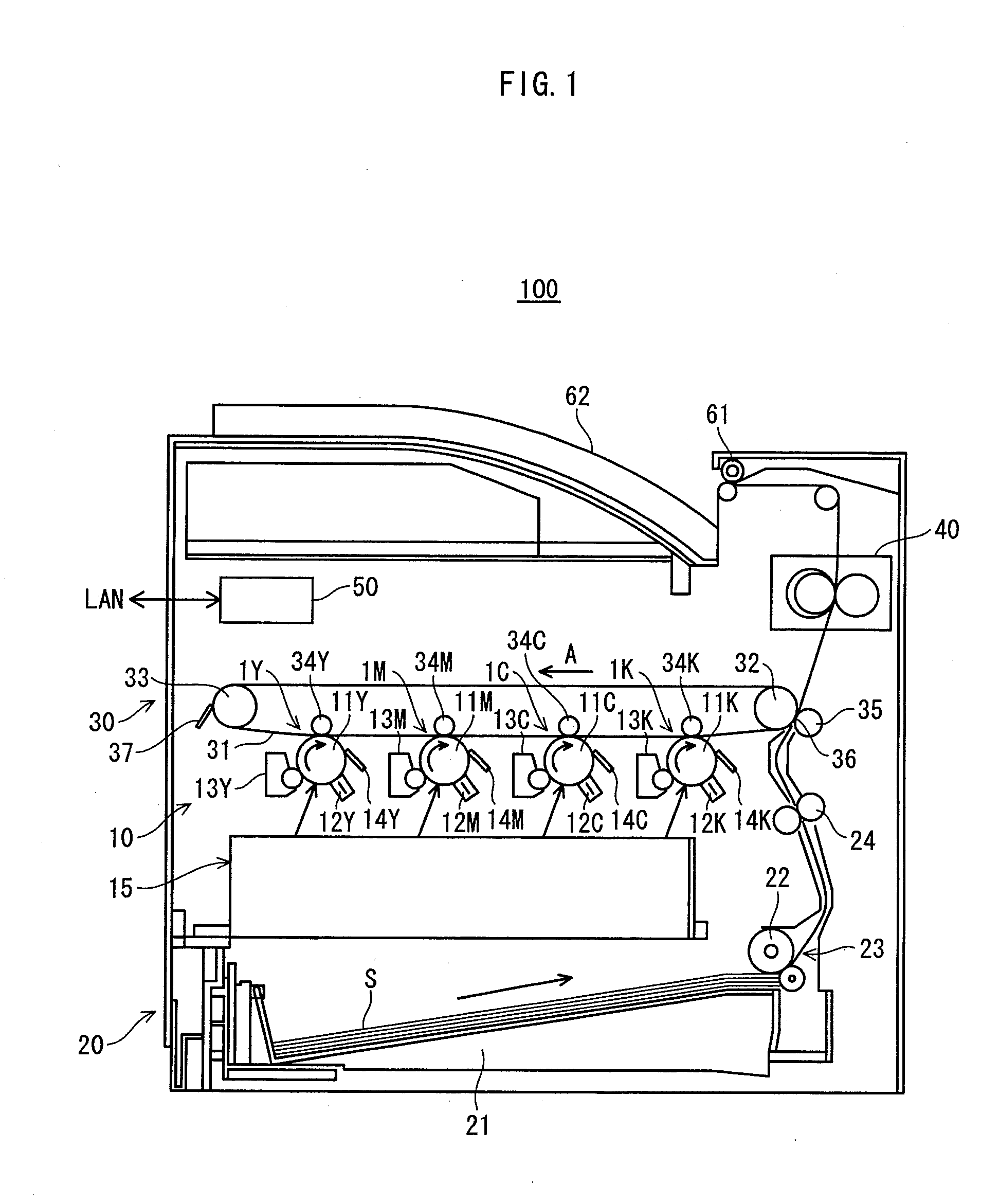
[0025]FIG. 1 is an outline cross-sectional view showing an overall structure of a printer 100 relating to embodiments of the present invention. The printer 100 includes an image forming unit 10, a paper feed unit 20, a transfer unit 30, a fixing device 40, a control unit 50, and so on.

[0026]The printer 100 is connected to a network such as a LAN (Local Area Network). Upon receiving an instruction to execute a print job from an external terminal apparatus (not shown), the printer 100 performs full-color image formation by forming toner images of cyan, magenta, yellow, and black colors, and multiple-transferring the formed toner images.

[0027]Hereinafter, the cyan, magenta, yellow, and black reproduction colors are represen...

embodiment 2

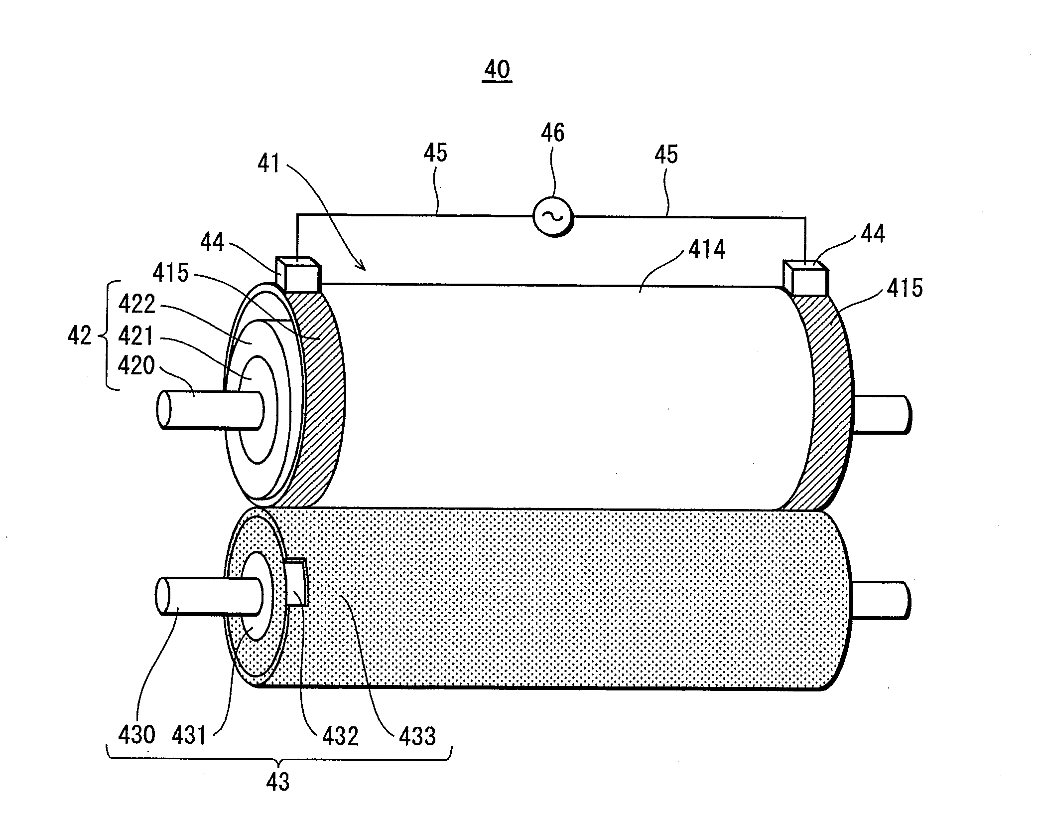
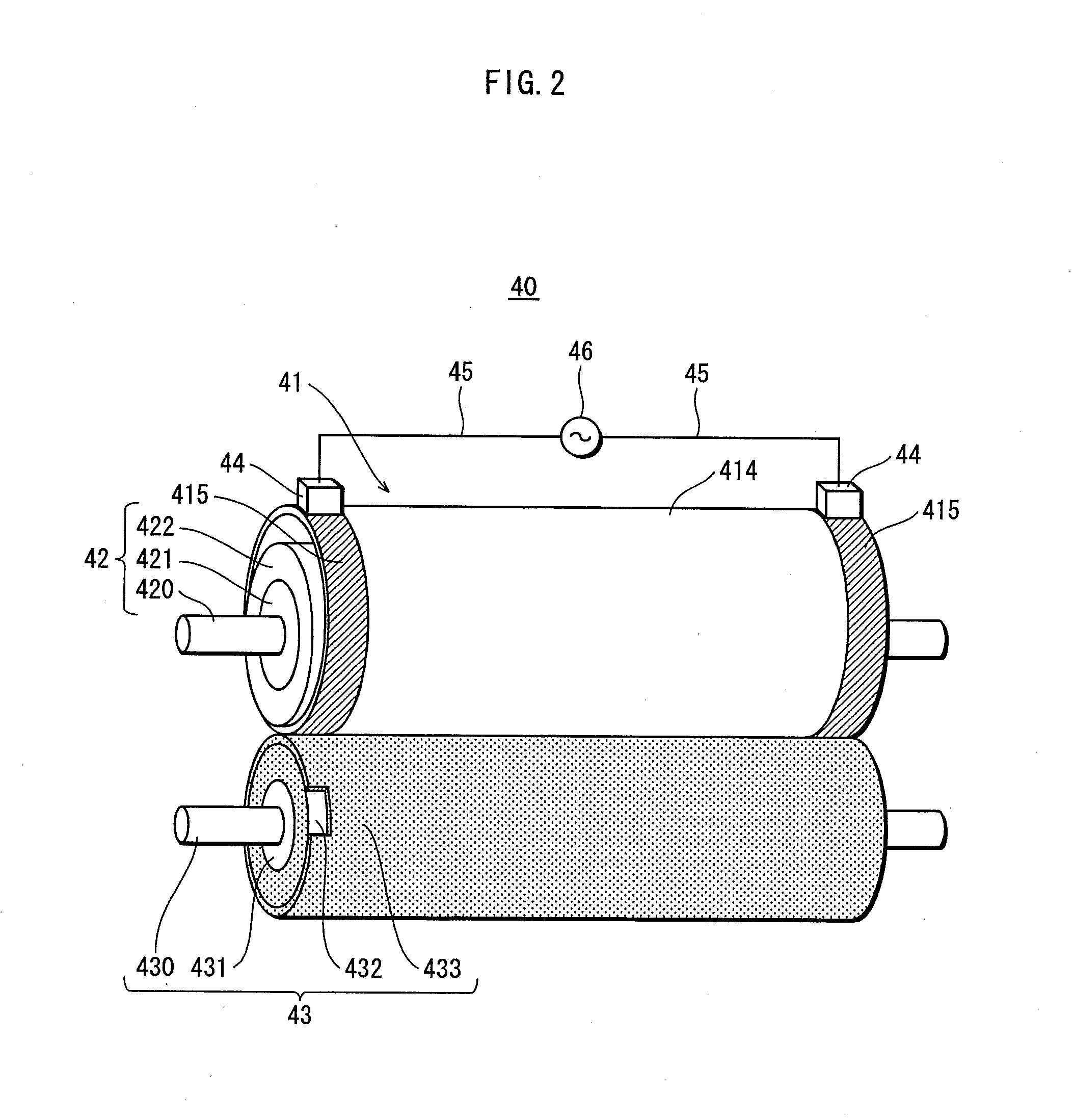
[0075]The above Embodiment 1 has described the structure in which the electrode 415 is included in the heat fixing belt 41. An Embodiment 2 describes the structure in which the electrode 415 is included in a roller.

[0076]In order to avoid duplication of the description, structural elements that are equivalent to their counterparts in the Embodiment 1 are assigned the same referential numerals, and description thereof is omitted here.

[0077]FIG. 8 is a schematic view showing the outline structure of a fixing device 70 relating to the Embodiment 2. The fixing device 70 has a structure in which the pressurizing roller 43 is forced by a forcing mechanism (not shown) toward the heating roller 71 as a heating rotary member to form a fixing nip. On the entire outer circumferential surface of each end of the heating roller 71 in the shaft direction, the electrode 715 is provided. The power feeding member 44 is pressed by the elastic member 491 to the electrode 715.

[0078]FIG. 9 is a partially...

modification examples

[0082]Although the present invention has been described based on the above embodiments, the present invention is not of course limited to the above embodiments, and the following modification examples may be employed.

[0083]Note that, in the following modifications, in order to avoid duplication of the description, structural elements that are equivalent to their counterparts in the Embodiments 1 and 2 are assigned the same referential numerals, and description thereof is omitted here.

[0084](1) In the above Embodiments 1 and 2, the electrode 415 has a double-layered structure. Alternatively, the electrode 415 may have a structure of three or more layers. In such a case, it is preferable that each layer is formed of metal having a low electrical resistivity and an electrode layer contacting the resistance heating layer 412 is formed of metal having a small difference in linear expansion coefficient from the binder resin that is the base material of the resistance heating layer 412. Fu...


PUM


Abstract

A fixing device includes: a heating rotary member having a heating layer generating heat upon current application; a pressurizing rotary member brought into pressure-contact with an outer circumferential surface of the heating rotary member to form fixing nip, through which a sheet on which unfixed toner image is formed passes for heat fixing; circular electrodes that are circumferentially formed at two respective positions sandwiching a sheet passing region therebetween, on the outer circumferential surface, and feed electrical power to the heating layer, the electrodes are each metallic and formed of at least two electrode layers including a first electrode layer layered directly on the heating layer and a second electrode layer as an outermost layer, linear expansion coefficient difference between the first layer and the heating layer is smaller than that between the second layer and the heating layer, and the second layer is more oxidation-resistant than the first layer.

Description

[0001]This application is based on an application No. 2010-57108 filed in Japan, the contents of which are hereby incorporated by reference.BACKGROUND OF THE INVENTION[0002](1) Field of the Invention[0003]The present invention relates to an electrode, which is for feeding an electrical power to a resistance heating layer, for use in an image forming apparatus and particularly in a fixing device.[0004](2) Description of the Related Art[0005]An image forming apparatus such as a copy machine includes a fixing device for causing an unfixed image formed on a recording sheet to pass through a nip member formed by a heating rotary member and a pressurizing rotary member to fix the unfixed image onto the recording sheet. In recent years, in view points of energy saving and heating speed-up, there has been proposed a fixing method of using, as a heating rotary member, an endless belt including a resistance heating layer. This resistance heating layer is composed of a mixture of conductive ma...

Claims


Application Information

Patent Timeline
Patent Type & Authority Applications(United States)
IPC IPC(8): G03G15/20
CPCG03G2215/2035G03G15/2064
Inventor HAYASE, TORUYAMAMOTO, NAOKIYONEKAWA, NOBORUFUKAYA, MAMORU
Owner KONICA MINOLTA BUSINESS TECH INC
Why Eureka
Try Eureka