Method of drying honeycomb formed body

Active Publication Date: 2011-09-22
NGK INSULATORS LTD
View PDF19 Cites 18 Cited by
  • Summary
  • Abstract
  • Description
  • Claims
  • Application Information

AI Technical Summary

Benefits of technology

[0025]According to a method of drying a honeycomb formed body of the present invention, deterioration of a cross-sectional shape, partially caused diameter differences, dents in an outer periphery, o

Problems solved by technology

In the dielectric drying, densities of electric lines of force that pass through the honeycomb formed body easily become non-uniform, thereby partial drying d

Method used


Image

  • Method of drying honeycomb formed body
  • Method of drying honeycomb formed body
  • Method of drying honeycomb formed body

Examples


examples

[0056]Hereinafter, the present invention will be described in more detail based on examples, but it is not limited to these examples.

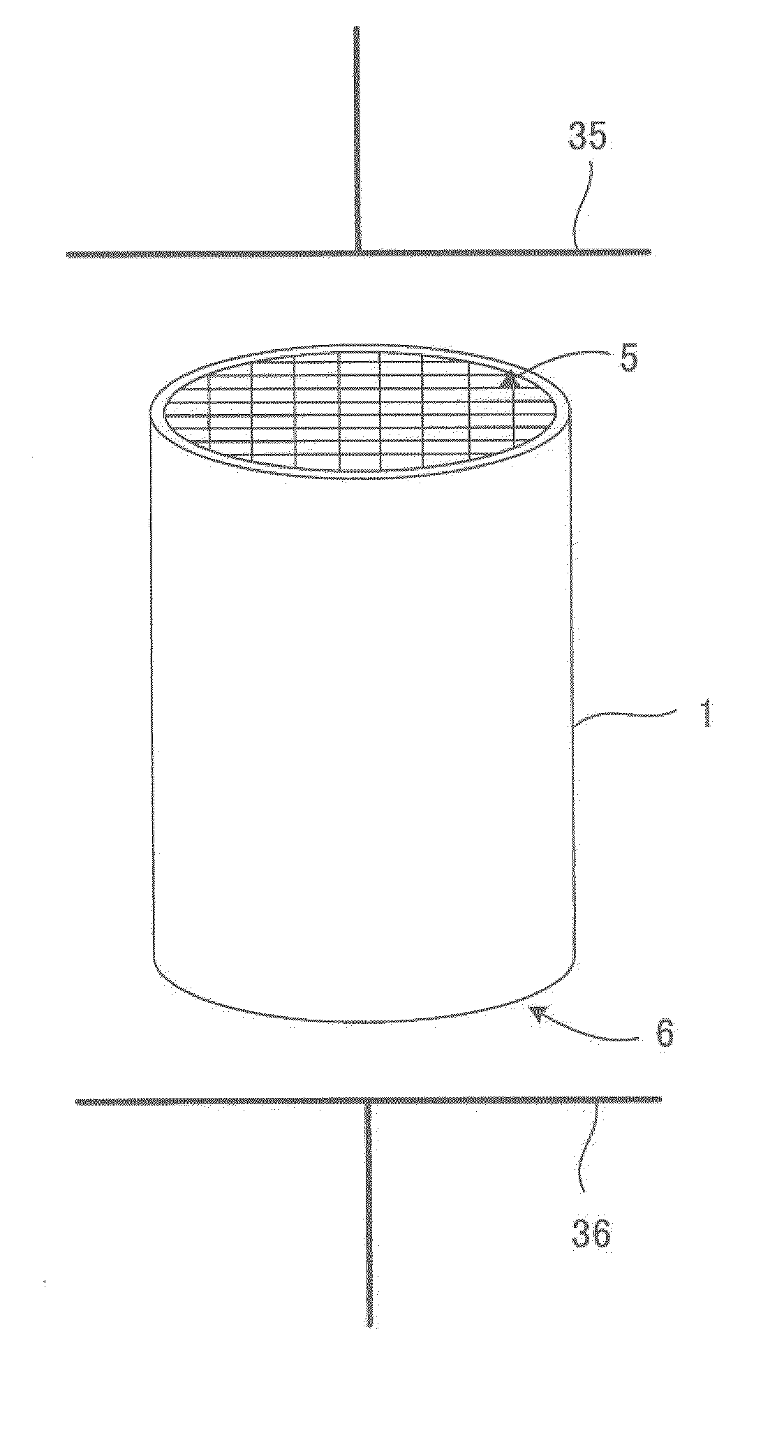
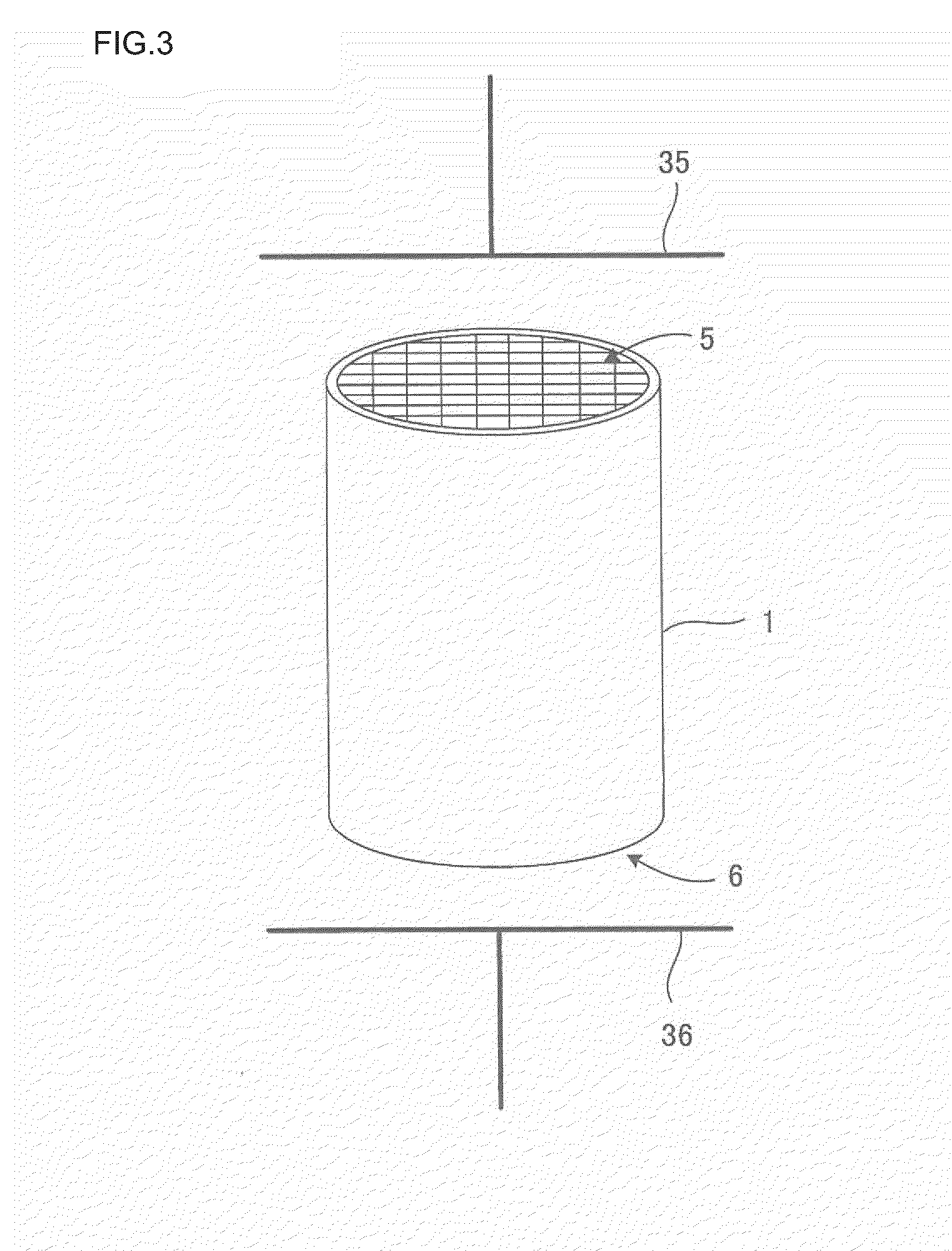
[0057](Experiment 1) Under the following conditions, a drying experiment was performed with which an output of a dielectric drying apparatus was set to be constant, the number of honeycomb formed bodies in a dry space was changed to thereby change a power density, and an effect on an appearance of the dried honeycomb formed body was examined.

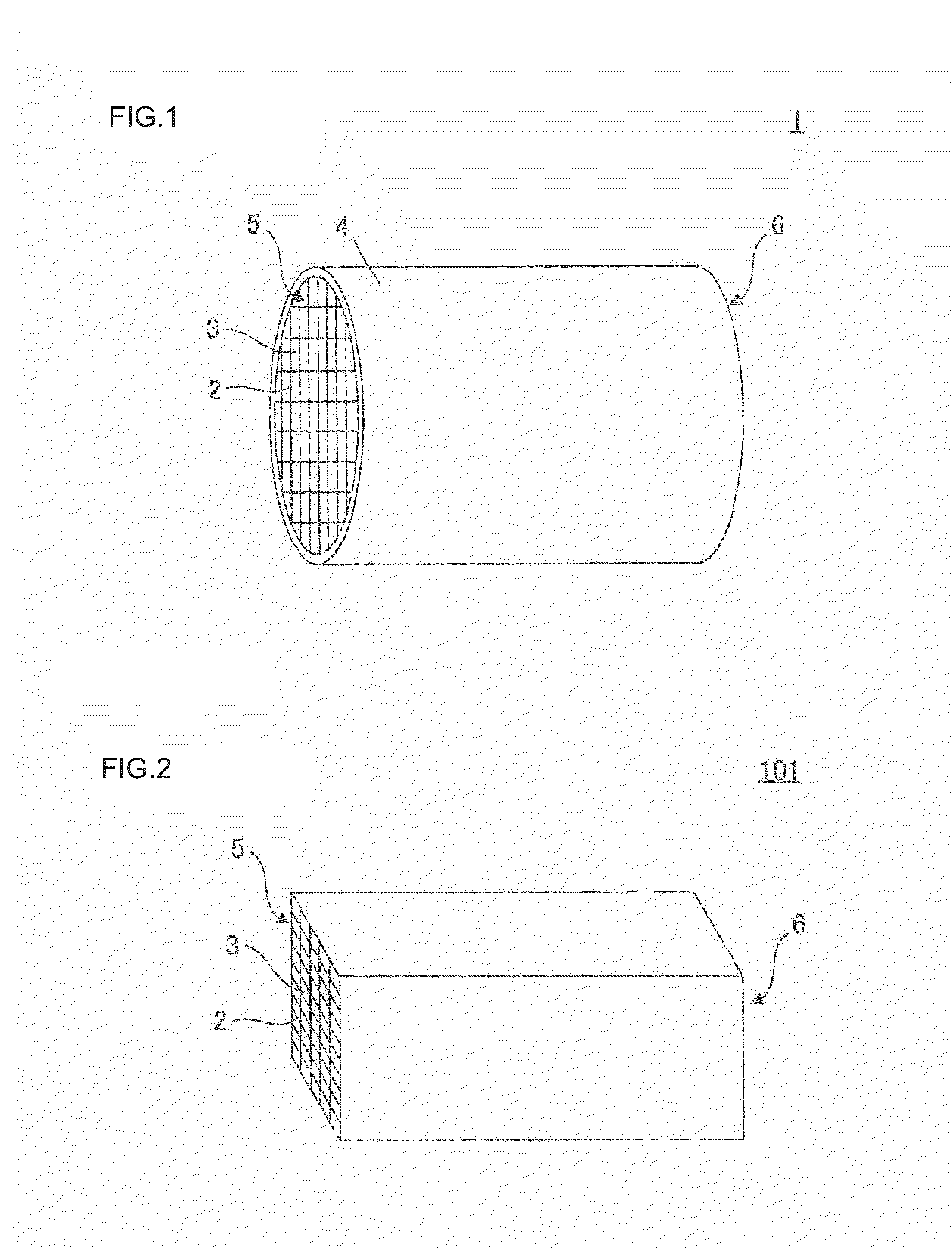
[0058][Honeycomb formed body] A cordierite raw material obtained by mixing alumina, kaolin, and talc was used as a ceramic material, and an auxiliary forming agent containing 7 parts by mass of methylcellulose as an organic binder, an addition agent, and water as a dispersion medium were mixed and kneaded to obtain kneaded clay. The obtained clay was extrusion-molded, and such a honeycomb formed body was obtained that a diameter was 120 mm, a length (axial length) was 180 mm, an outline shape was a cylinder, and a ...


PUM

PropertyMeasurementUnit
Temperatureaaaaaaaaaa
Fractionaaaaaaaaaa

Abstract

A method of drying a ceramic formed body comprising the step of performing dielectric drying on an unfired honeycomb formed body formed with a ceramic material as a main raw material under a condition that a power density is 5 to 20 [kW/kg (water)].

Description

BACKGROUND OF THE INVENTION[0001]1. Field of the Invention[0002]The present invention relates to a method of drying honeycomb formed bodies. More specifically, the present invention relates to a method of drying honeycomb formed bodies with which they cannot easily be affected by an atmosphere in a dry space and can be dried without occurrence of deformation and cracks of outer peripheries thereof even when partition walls thereof are thin.[0003]2. Related Background of the Invention[0004]A honeycomb structure made of ceramics has been widely used for catalyst carriers, various filters, etc. Recently, the honeycomb structure has particularly attracted the attention as a diesel particulate filter (DPF) for capturing particulate matters discharged from a diesel engine.[0005]Such honeycomb structure can generally be obtained by kneading a raw material composition obtained through addition of an auxiliary forming agent and various addition agents to a ceramic material and dispersion med...

Claims


Application Information

Patent Timeline
IPC IPC(8): B29C71/04
CPCF26B3/343F26B3/347F26B15/16F26B2210/02B28B11/243C04B35/6263C04B35/6365C04B2235/606B28B11/241C04B35/195C04B38/0006C04B2111/00793C04B38/0054
Inventor OKUMURA, KENSUKETAKAGI, SHUICHI
Owner NGK INSULATORS LTD
Why Eureka
Try Eureka