Vehicular charging system

a charging system and electric motor technology, applied in hybrid vehicles, battery/fuel cell control arrangements, propulsion by batteries/cells, etc., can solve problems such as the problem of how electric power is distributed among the respective power storage devices, and achieve the effect of suppressing energy efficiency

Active Publication Date: 2011-09-22
TOYOTA JIDOSHA KK
View PDF4 Cites 32 Cited by
  • Summary
  • Abstract
  • Description
  • Claims
  • Application Information

AI Technical Summary

Benefits of technology

[0021]According to the present invention, charging the power ...

Problems solved by technology

When the plurality of power storage devices are mounted in this manner, how elec...

Method used


Image

  • Vehicular charging system
  • Vehicular charging system
  • Vehicular charging system

Examples


first embodiment

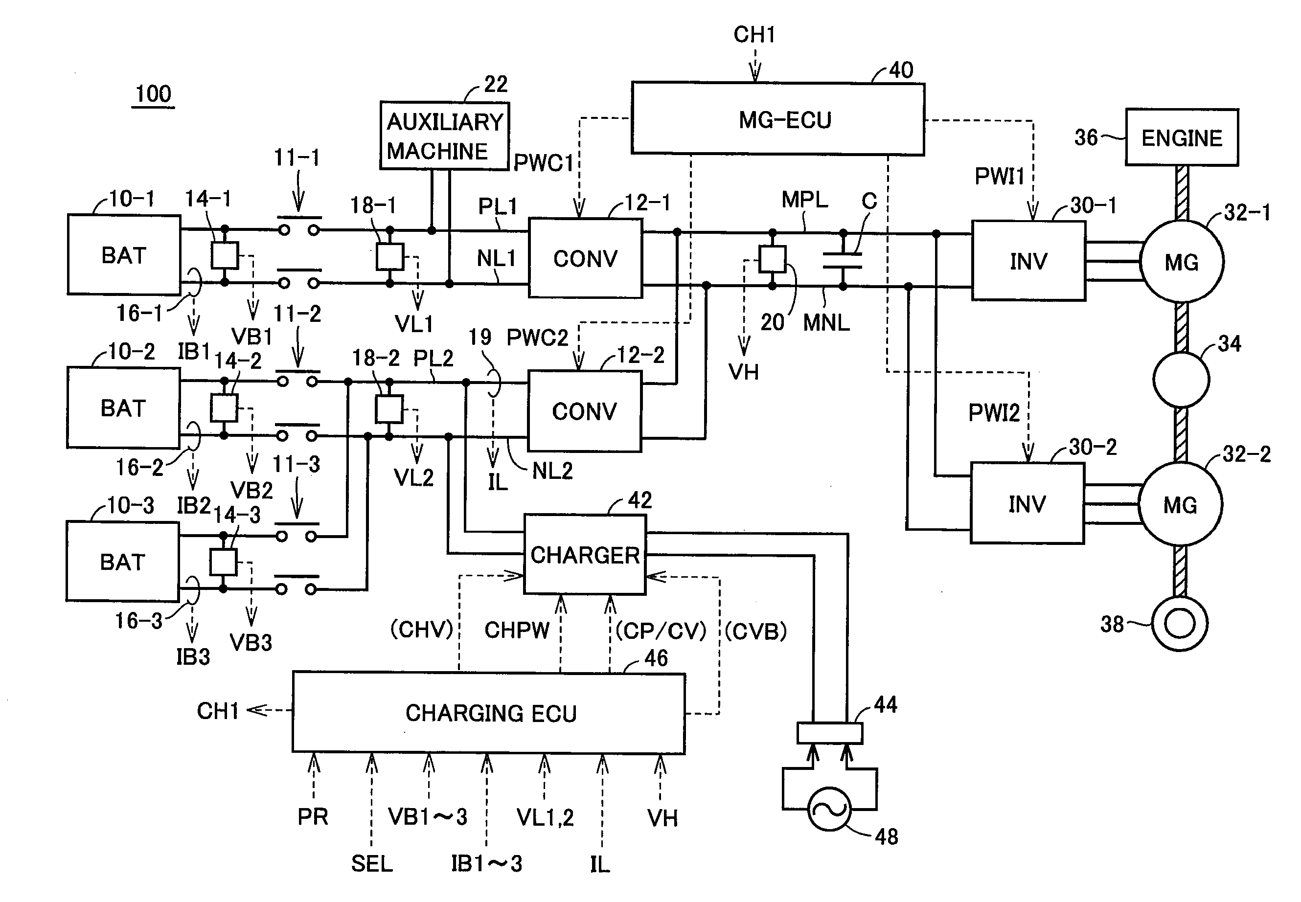
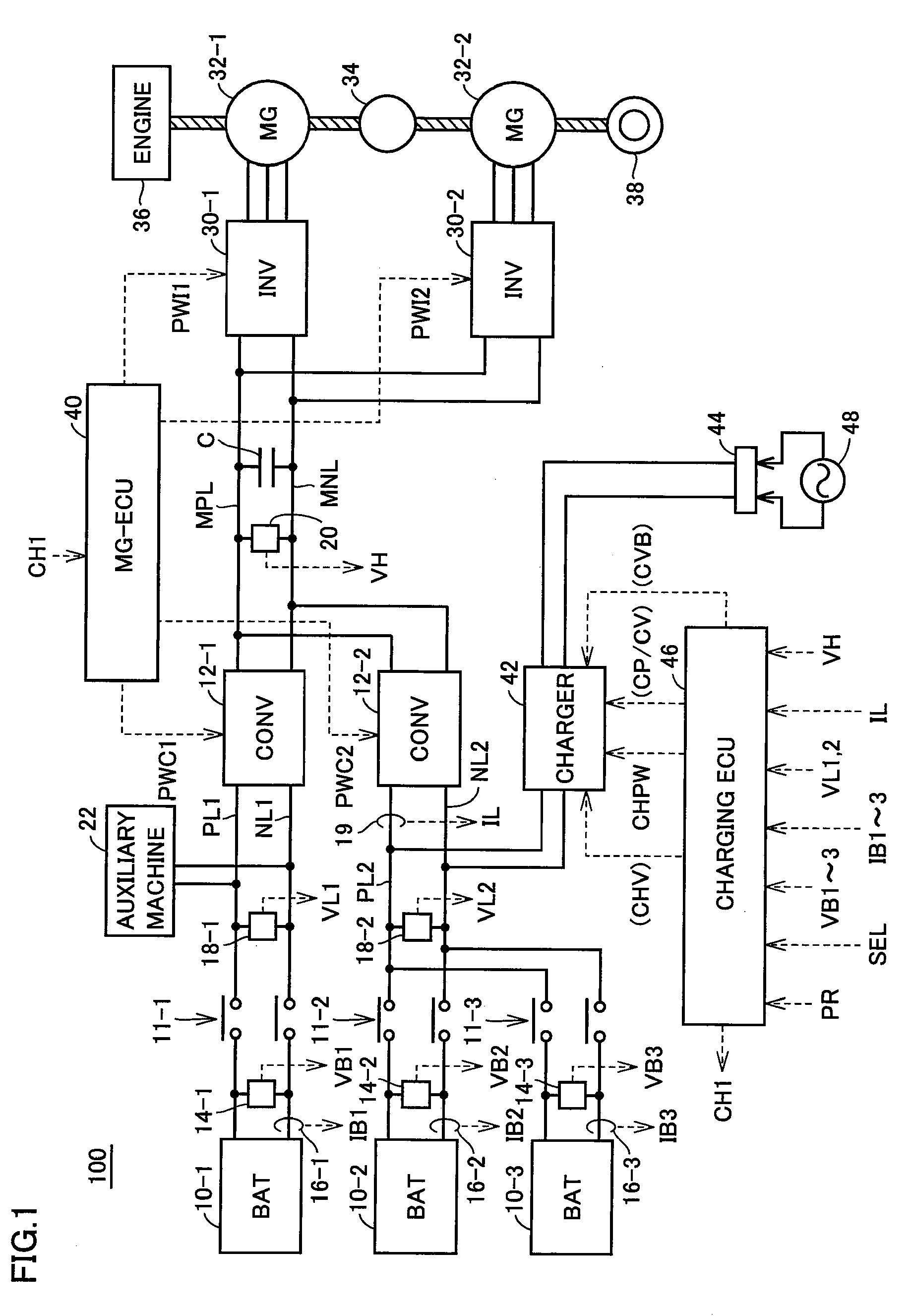
[0032]FIG. 1 is an overall block diagram of a hybrid vehicle shown as one example of an electric powered vehicle according to the present invention.

[0033]Referring to FIG. 1, a hybrid vehicle 100 includes power storage devices 10-1 to 10-3, system main relays 11-1 to 11-3, converters 12-1 and 12-2, a main positive bus MPL, a main negative bus MNL, a smoothing capacitor C, and an auxiliary machine 22. In addition, hybrid vehicle 100 further includes inverters 30-1 and 30-2, motor generators 32-1 and 32-2, a power split device 34, an engine 36, and a driving wheel 38. Furthermore, hybrid vehicle 100 includes voltage sensors 14-1 to 14-3, 18-1, 18-2 and 20, current sensors 16-1 to 16-3 and 19, and an MG-ECU (Electronic Control Unit) 40. Moreover, hybrid vehicle 100 includes a charger 42, a vehicle inlet 44 and a charging ECU 46.

[0034]Each of power storage devices 10-1 to 10-3 is a rechargeable DC power supply and includes, for example, a secondary battery such as a nickel-metal hydride...

second embodiment

[0090]In a second embodiment, it is further determined when to complete charging, by comprehensively determining a relationship between the charging efficiency and the amount of energy that can be charged.

[0091]FIG. 8 is a flowchart for describing charging completion determination processing executed in the second embodiment.

[0092]Although this charging completion determination processing can be used in charging in steps S3, S4 and S5 in FIG. 4, this charging completion determination processing can be used to determine completion of charging in not only the configuration having a plurality of power storage devices as shown in FIG. 1 but also various plug-in hybrid vehicles. Referring to FIG. 8, when the process starts, the charging efficiency at the present time is first calculated in step S21. A charging efficiency K herein is calculated by the following equation:

charging efficiency K (%)=(charging power) / (supplied power)  (1)

[0093]The charging power herein refers to electric power...


PUM


Abstract

A charging ECU causes a charger to perform quick charging until a state of charge of a power storage device reaches a predetermined state. The charging ECU causes the charger to perform additional charging during which charging progresses more slowly than the quick charging, when the state of charge comes closer to full charge than the predetermined state. The charging ECU stops charging of the power storage device by the charger when the state of charge of the power storage device reaches a charging stop threshold value during the additional charging, and stops charging of the power storage device by the charger when a time of the additional charging exceeds a predetermined time even if the state of charge of the power storage device does not reach the charging stop threshold value.

Description

TECHNICAL FIELD[0001]The present invention relates to a vehicular charging system, and in particular, to a charging system for a vehicle provided with a power storage device configured to be chargeable from outside the vehicle.BACKGROUND ART[0002]In electric vehicles and hybrid vehicles, mounting a plurality of power storage devices and extending the distance (EV drive distance) that can be traveled without operating an engine has been contemplated. When the plurality of power storage devices are mounted in this manner, how electric power is distributed among the respective power storage devices becomes a problem.[0003]Japanese Patent Laying-Open No. 2008-109840 discloses a power supply system for a vehicle provided with a plurality of power storage devices. In this power supply system, a discharge share ratio calculation unit calculates remaining electric power quantities of the respective power storage devices before a state of charge (SOC) with respect to which the allowable disc...

Claims


Application Information

Patent Timeline
IPC IPC(8): H02J7/04B60L50/15B60L50/16
CPCB60K6/445Y02T90/14B60L11/14B60L11/1816B60L11/185B60L11/1868B60L15/007B60W10/26B60W20/00H02J7/0013H02J7/0073Y02T10/6217Y02T10/6239Y02T10/6269Y02T10/7005Y02T10/7055Y02T10/7066Y02T10/7077Y02T90/121Y02T90/128B60L11/123B60L15/2045B60L50/16B60L50/61B60L53/11B60L53/14B60L58/15B60L58/20H02J7/0071Y02T10/62Y02T10/64Y02T10/70Y02T10/7072Y02T10/72B60W2510/244B60W20/13Y02T90/12
Inventor MITSUTANI, NORITAKE
Owner TOYOTA JIDOSHA KK
Why Eureka
Try Eureka