Magnetic resonance imaging system with satellite gradient coils

a magnetic resonance imaging and gradient coil technology, applied in the field of magnetic resonance imaging systems, can solve the problems of increasing the required input power, the cost of gradient amplifier driving, and the inability to make a trade-off between cost and patient space available,

Active Publication Date: 2011-09-22
KONINKLIJKE PHILIPS ELECTRONICS NV
View PDF18 Cites 8 Cited by
  • Summary
  • Abstract
  • Description
  • Claims
  • Application Information

AI Technical Summary

Benefits of technology

[0008]The present invention has the advantage that the gradient coil conductors are kept at a small radius wherever this is possible leaving sufficient space at the step formed by the first satellite coil and the inner coil for an RF body coil, thus optimizing its efficiency and reducing cost of the gradient amplifier. Near the centre, where the RF coil can be located, the inner radius is bigger, while at one coil end the radius preferably is made approximately equal to the RF coil radius. Further, by spatially splitting and distributing the pairs of saddle coils onto the first satellite coil, a highly efficient x and / or y gradient coil system can be provided—the gradient field distribution in the MR bore is maintained in an optimal manner, since additionally the inner coil is present, while the self inductance of the gradient coil system is reduced. Further, since the first satellite coil and the inner coil form a stepped structure, an RF body coil be easily inserted from the ‘open end’ of the gradient coil system into the recess formed by the inner coil with its larger diameter than the first satellite coil. Here, the ‘open end’ is understood as the end of the gradient coil system opposed to the side at which the first satellite coil is located. It has to be noted, that the first satellite coil and the inner coil do not necessarily have to overlap. However, the first satellite coil and the inner coil can be partially overlapping.
[0010]Due to the preferably (but not necessarily) symmetric arrangement of the first and second satellite coil, as well as the inner coil, a highly efficient gradient coil system can be provided. Further, preferably the X and Y axes of the gradient coil system each comprise a first and a second spatially separated satellite coil and an inner coil.
[0012]While the first and / or second satellite coil mainly functions to generate a predetermined gradient magnetic field in the homogeneous magnetic field area of the magnet bore in which an object is to be imaged, the shielding coil functions as to generate a magnetic field which cancels the magnetic fields generated by the satellite coils and to prevent leaking of the gradient coil field towards the superconducting magnet surrounding the shielding coil(s). Since the shielding coil—which typically also comprises two sets of saddle coils—overlaps the first and / or the second satellite coils, i.e. since the ‘length’ of the shielding coils in the direction of the longitudinal axis of the main magnet is larger or equal than the distance at which the satellite coil edges averted from each other are spaced apart from each other, a gradient coil system is provided of which the effect is the same or even improved over the complete volume commonly covered by the satellite coils and the shielding coil as if it would be, in case two state of the art gradient and shielding coils would be applied.
[0015]In accordance with an embodiment of the invention, the inner coil extends over the first and / or second satellite coil. For example, the ‘length’ of the inner coil in the direction of the longitudinal axis of the main magnet is larger or equal than the distance at which the satellite coil edges averted from each other are spaced apart from each other. This further ensures that a possible efficiency reduction of the satellite coils arrangement is compensated by the additional presence of the inner coil which extends over the satellite coil(s).
[0018]The serial connection of the first and / or second satellite coil with the inner coil and / or the shielding coil over the preferred inclined structural flanges has the advantage that the extension of the satellite coils in z direction, i.e. in the direction of the longitudinal axis of the main magnet, can be further reduced, without taking a loss in gradient coil efficiency. As a consequence, the total spatial dimensions of the gradient coil system are reduced which further enhances a patient comfort, since more space is thus provided in the MR bore accommodating the patient (or in general the object to be imaged). Preferably, in order the improve the gradient coil efficiency, the flanges are inclined towards each other and towards the centre of the magnet bore, wherein the flanges are arranged on the opposed edges of the satellite coils.
[0020]In accordance with an embodiment of the invention, the first and / or second satellite coils are serially electrically connected with the inner coil and / or the shielding coil over paired electrical connections, the electrical connections extending perpendicularly from the surface formed by the saddle coils, wherein the two electrical connections of a pair of electrical connections carry opposed currents. This has the advantage, that currents running through the electrical connections generate mutually compensating magnetic fields, such that the gradient fields generated by the gradient coil(s) are not disturbed in an unwanted manner.

Problems solved by technology

Increasing the inner radius of the gradient coil drastically increases the required input power per gradient field, and therefore cost of the gradient amplifier driving it.
Thus, a tradeoff has to be made between cost and available patient space.

Method used


Image

  • Magnetic resonance imaging system with satellite gradient coils
  • Magnetic resonance imaging system with satellite gradient coils
  • Magnetic resonance imaging system with satellite gradient coils

Examples


Embodiment Construction

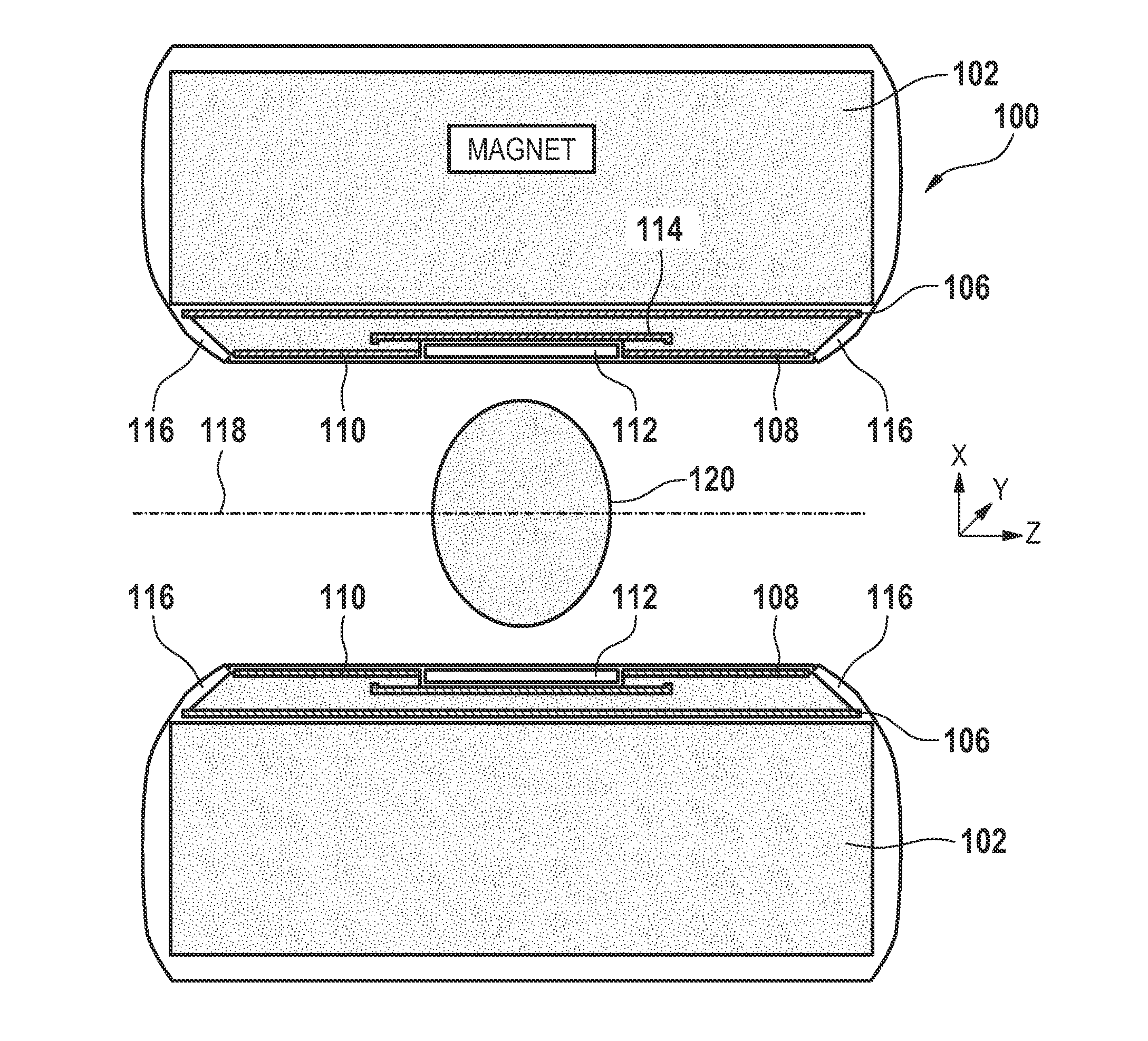
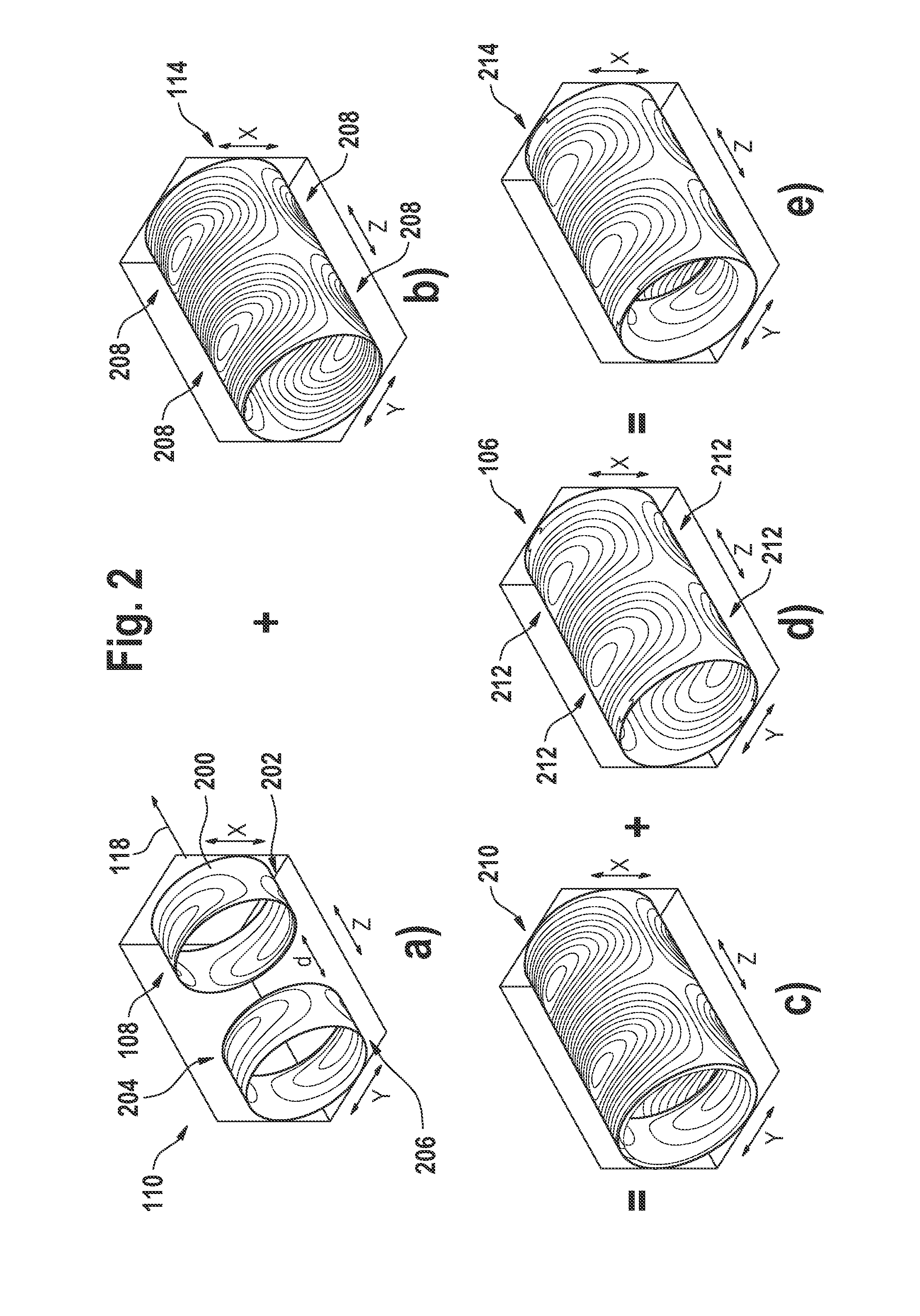
[0028]In the following, similar elements are depicted by the same reference numerals. Further, in the following it is assumed that without loss of generality two satellite coils are used in a symmetric manner. However, the basic principle underlying the invention can also be used with only one single satellite coil and an inner coil.

[0029]FIG. 1 is a schematic of a cross section of an MR system 100 comprising a main magnet 102 and a gradient coil system. In the following, MR system is understood as the structural arrangement comprising a support which carries the main magnet 102 with its magnet bore, carries the gradient coils, as well as optionally various kinds of electronics like amplifiers, filters, reception coils 112.

[0030]As can be seen in FIG. 1, the MR system 100 comprises a main magnet 102, which is adapted for generating a homogeneous main magnetic field B0 within an imaging volume 120 the magnet bore, wherein an object to be imaged is to be placed at least within the ima...


PUM


Abstract

The present invention relates to a magnetic resonance imaging system comprising a main magnet (102), the main magnet (102) comprising a magnet bore, the bore having a longitudinal axis (118) parallel to the main magnetic field of the main magnet (102), the magnet bore comprising a gradient coil system, wherein the gradient coil system comprises a first (108) satellite coil and an inner coil (114), wherein the first satellite coil comprises at least one pair of saddle coils (200; 202; 204; 206) arranged oppositely over the magnet bore and wherein the inner coil (114) comprises at least two pairs of saddle coils (208) arranged oppositely over the magnet bore, wherein the inner coil (114) is located at a larger diameter from the central axis (118) than the first (108) satellite coil, wherein the first satellite coil and the inner coil form a stepped coil structure.

Description

TECHNICAL FIELD[0001]The present invention relates to a magnetic resonance imaging system.BACKGROUND AND RELATED ART[0002]Magnetic resonance imaging (MRI) is a state of the art imaging technology which allows cross sectional viewing of objects like the human body with unprecedented tissue contrast. MRI is based on the principles of nuclear magnetic resonance (NMR), a spectroscopic technique used by scientists to obtain microscopic chemical and physical information about molecules. The basis of both NMR and MRI is the fact, that atomic nuclei with none zero spin have a magnetic moment. In medical imaging, usually nuclear hydrogen atoms are studied since they are present in the body in high concentrations for example water. The nuclear spin of elementary particles can resonate at a resonance frequency, if a strong DC magnetic field (B0 field) is applied. The magnetic resonance (MR) frequency is determined by the level of the magnetic flux. In an MRI scanner, the magnetic field matches...

Claims


Application Information

Patent Timeline
Patent Type & Authority Applications(United States)
IPC IPC(8): G01R33/44
CPCG01R33/56572G01R33/385
Inventor KONIJN, JANMULDER, GERARDUS BERNARDUS JOZEF
Owner KONINKLIJKE PHILIPS ELECTRONICS NV
Why Eureka
Try Eureka