Auto Stereoscopic 3D Telepresence Using Integral Holography

a technology of integral holography and stereoscopic video, which is applied in the field of 3d telepresence systems and methods, can solve the problems that the viewer cannot explore different perspectives of the scene, the standard video conferencing does not try to produce illusions, and the musion eyeliner® system cannot reproduce perspective or parallax, etc., to achieve the effect of increasing the brightness of the hologram, improving the diffraction efficiency of the holographic material, and improving throughpu

Active Publication Date: 2011-09-22
TIPD +1
View PDF9 Cites 72 Cited by
  • Summary
  • Abstract
  • Description
  • Claims
  • Application Information

AI Technical Summary

Benefits of technology

[0026]The present invention provides a system and method for continuous presentation of auto stereoscopic integral holograms at video or sub-video refresh rates. The holographic direct-view display system uses a holographic integral imaging technique that is an auto stereoscopic way to reproduce parallax and occlusion. The display is not resolution limited and may be scalable to display life size images if desired. The system can be used to transmit 3D depictions of a scene at video and sub-video rates as well as other information, such as images of documents or computer generated images. The images may be captured, transmitted and displayed in real-time (or near real-time) for a telepresence application or stored for time-shifted display for other applications (e.g. movie theaters). The system combines integral holography, a pulsed laser to record the hologram at high speed and a dynamic refreshable holographic material such as a photorefractive polymer as a recording media. The system uses techniques to write, read and erase the updateable hologram that allow the holographic material, hence direct-view display to remain stationary throughout each of the processes for continuous presentation of the sequence of holograms to the audience at video or sub-video rates. The system may write, read and erase at the same time and continuously to increase throughput. This system may also use additional novel techniques to improve brightness, efficiently implement a full-parallax display and to implement a full-color display in a transmission geometry.
[0028]In an embodiment, the stationary holographic material is illuminated with the reading beam to continuously present the hologram to the audience. The write beam is steered from one position to the next to record the next hogel. When the last hogel of the current hologram has been recorded the write beam is encoded and steered to write the first hogel of the next hologram. The write beam may also function to simultaneously erase the previous hologram while it records the new hologram. Alternately, every other pulse of the write beam could be used to erase the hogel. Each hogel position would first be addressed with an erase pulse and then with the pulse encoded with the hogel data. Alternately, a separate focused erase beam may either lead the write beam or may be pulsed and interlaced in time with the pulsed write beam to erase the next hogel just prior to writing. Accordingly, the holographic material does not have to move from position to position to write each hogel, to move to a different location to read the hologram and yet another location to erase the hologram. Furthermore, this approach provides for the writing and reading of the hologram and writing and erasing of the hologram to be performed at the same time that improves throughput.
[0029]In an embodiment in which the system is configured for a transmission recording geometry, the entire hologram may be read while individual hogels are being recorded by placing a mask / mirror between the writing source and the holographic material and positioning the reading source on the other side of the holographic material (viewer side). The mask / mirror is formed with aperture (entire line for HPO or single line segment for full-parallax). The mask / mirror moves with the steered write beams so that the object and reference beams pass through the slit and interfere at the specified position to write the encoded hogel. The mask prevents any of the write beam from illuminating neighboring hogels. The mask / mirror is formed with a reflective surface facing the holographic material and reading source so that the reading beam is reflected and transmitted through the holographic material. A filter may be positioned between the holographic material and the audience to remove any of the write beam that is not absorbed by the holographic material.
[0030]In an embodiment, a holographic optical element (HOE) is placed between the holographic material and the write beam. The HOE is designed so that the object beam passes through the element unaffected but the reference beam is diffracted at an acute angle. This has the effect of increasing the diffraction efficiency of the holographic material, which in turn increases the brightness of the hologram.

Problems solved by technology

Standard video conferencing does not try to produce the illusion that connected locations are merged together for better interaction.
The Musion Eyeliner® system cannot reproduce perspective or parallax which are part of the realism for a telepresence display.
The viewer cannot explore different perspectives of the scene, which accounts for some lack of realism in the image.
The limitation of the integral imaging technique for telepresence is the degradation of the resolution of the display.
To obtain an acceptable resolution in the three dimensions the microlenses should be extra small (equal or lower than eye resolution) but should also cover a large amount of pixels, altogether, this means those pixels should be extremely small and numerous which is not technically possible.

Method used


Image

  • Auto Stereoscopic 3D Telepresence Using Integral Holography
  • Auto Stereoscopic 3D Telepresence Using Integral Holography
  • Auto Stereoscopic 3D Telepresence Using Integral Holography

Examples


Embodiment Construction

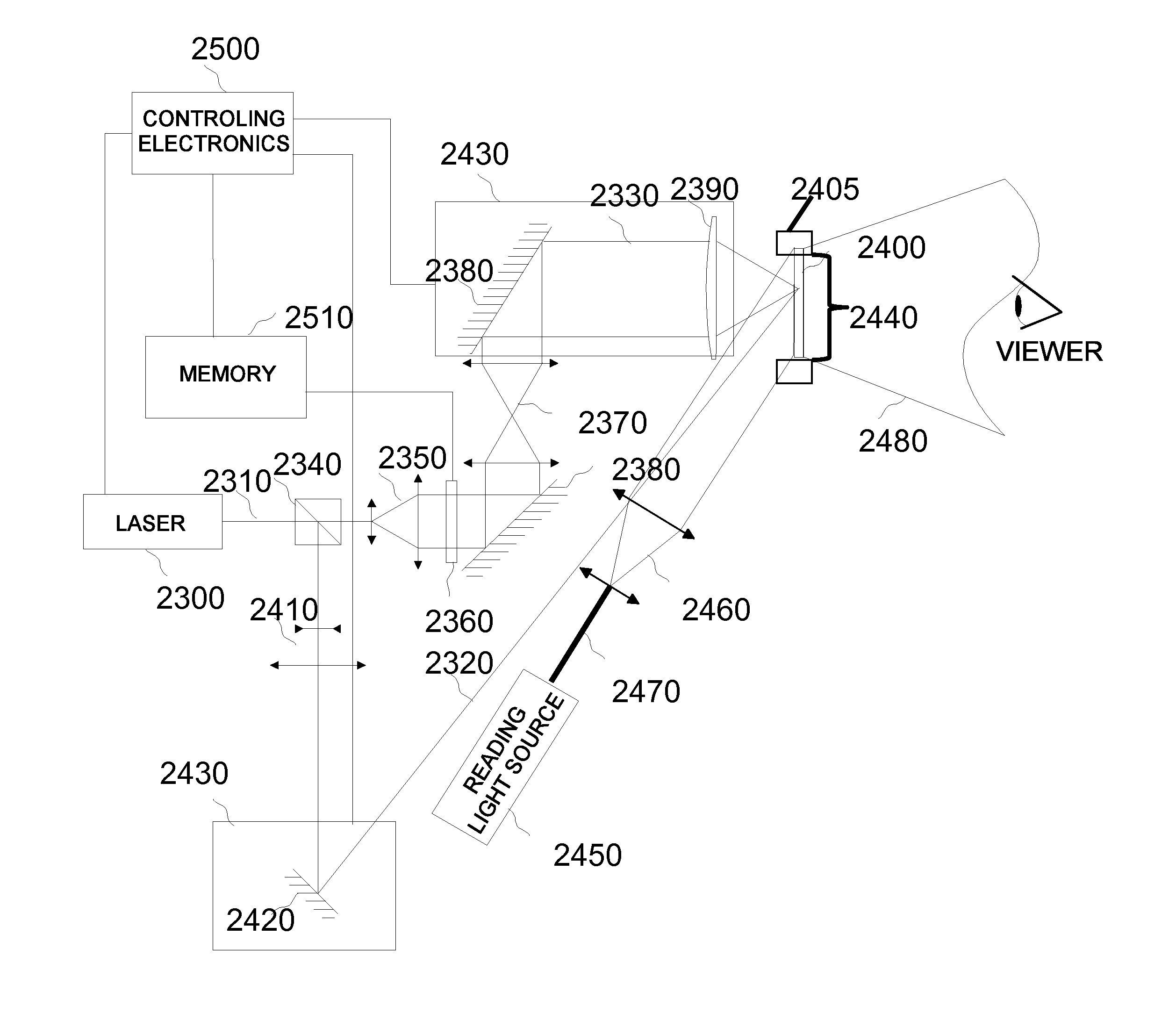
[0050]The present invention describes a holographic direct-view display system using a holographic integral imaging technique that is an auto stereoscopic way to reproduce parallax and occlusion. The display is not resolution limited and is scalable to display life size images if desired. The system can be used to transmit 3D depictions of a scene at video and sub-video rates as well as other information, such as images of documents or computer generated images. The images may be captured, transmitted and displayed in real-time (or near real-time) for telepresence or stored for time-shifted display. The system combines integral holography, a pulsed laser to record the hologram at high speed and a dynamic refreshable holographic material such as a photorefractive polymer as a recording media. The system uses techniques to write, read and erase the updateable hologram that allow the holographic material, hence direct-view display to remain stationary throughout each of the processes f...


PUM


Abstract

A holographic direct-view display system uses holographic integral imaging techniques that is an auto stereoscopic way to reproduce parallax and occlusion. The display is not resolution limited and is scalable to display life size images if desired. The system can be used to transmit 3D depictions of a scene at video and sub-video rates as well as other information, such as images of documents or computer generated images. The images may be captured, transmitted and displayed in real-time (or near real-time) for telepresence or stored for time-shifted display. The system combines integral holography, a pulsed laser to record the hologram at high speed and a dynamic refreshable holographic material such as a photorefractive polymer as a recording media. The system uses techniques to write, read and erase the updateable hologram that allow the holographic material, hence direct-view display to remain stationary throughout each of the processes for continuous presentation of the hologram to the audience. The system may write, read and erase at the same time and continuously to increase throughput. This system may also use additional novel techniques to improve brightness, efficiently implement a full-parallax display and to implement a full-color display in a transmission geometry.

Description

CROSS-REFERENCE TO RELATED APPLICATIONS[0001]This application claims benefit of priority under 35 U.S.C. 119(e) to U.S. Provisional Application No. 61 / 315,321 entitled “Auto Stereoscopic 3D Telepresence Using Integral Holography” and filed on Mar. 18, 2010, the entire contents of which are incorporated by reference.GOVERNMENT LICENSE RIGHTS[0002]This invention was made with Government support under FA9550-07-1-0071 awarded by the Air Force Office of Scientific Research, under W31P4Q-07-0267 awarded by the US Army Aviation & Missile Command, and under FA9550-09-C-0015 awarded by the Air Force Office of Scientific Research. The Government has certain rights in this invention.BACKGROUND OF THE INVENTION[0003]1. Field of the Invention[0004]This invention relates to systems and methods for 3D telepresence and other 3D display applications for moving images and more particularly to systems and methods for presenting auto stereoscopic integral holograms on a stationary direct-view display ...

Claims


Application Information

Patent Timeline
Patent Type & Authority Applications(United States)
IPC IPC(8): H04N7/15H04N5/89
CPCG03H1/0005G03H2001/0088G03H2001/0264G03H2001/2292G03H2001/2297G03H2210/22G03H2001/048G03H2260/36G03H2260/54G03H2001/0497G03H1/2645G03H1/268G03H2222/33
Inventor BLANCHE, PIERRE-ALEXANDRE JEANBABLUMYAN, ARKADYPEYGHAMBARIAN, NASSER N.
Owner TIPD
Why Eureka
Try Eureka