Apparatus and method for photoacoustic imaging

a technology of photoacoustic imaging and apparatus, applied in the field of apparatus and method for photoacoustic imaging, can solve the problems of difficult to achieve satisfactory effects, insufficient reduction of amplitude caused by multiple echoes in some cases, and hidden images of light absorbers, so as to reduce artifacts in images

Inactive Publication Date: 2011-09-29
CANON KK
View PDF21 Cites 37 Cited by
  • Summary
  • Abstract
  • Description
  • Claims
  • Application Information

AI Technical Summary

Benefits of technology

[0013]According to the present invention, signals in each of which signal amplitudes caused by an interfacial acoustic wave and a re

Problems solved by technology

Disadvantageously, an image of a light absorber may be hidden by an artifact caused by the transient response.
In an ultrasonic measuring apparatus using an ultrasonic echo, multiple reflections of a transmitted ultrasonic wave are repeated inside a member interposed between an acoustic wave detecting device and a specimen, thus causing artif

Method used


Image

  • Apparatus and method for photoacoustic imaging
  • Apparatus and method for photoacoustic imaging
  • Apparatus and method for photoacoustic imaging

Examples


first embodiment

[0031]According to a first embodiment of the present invention, received signals output from acoustic wave detecting devices arranged in an array are added to obtain a summed signal and the summed signal is normalized for each acoustic wave detecting device. The normalized signals and the received signals are used to reduce signal amplitudes caused by an interfacial acoustic wave and a reflected interfacial acoustic wave.

Configuration of Apparatus

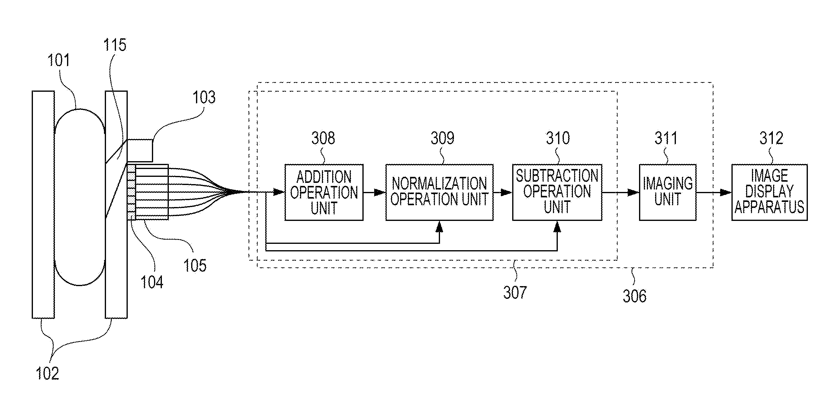
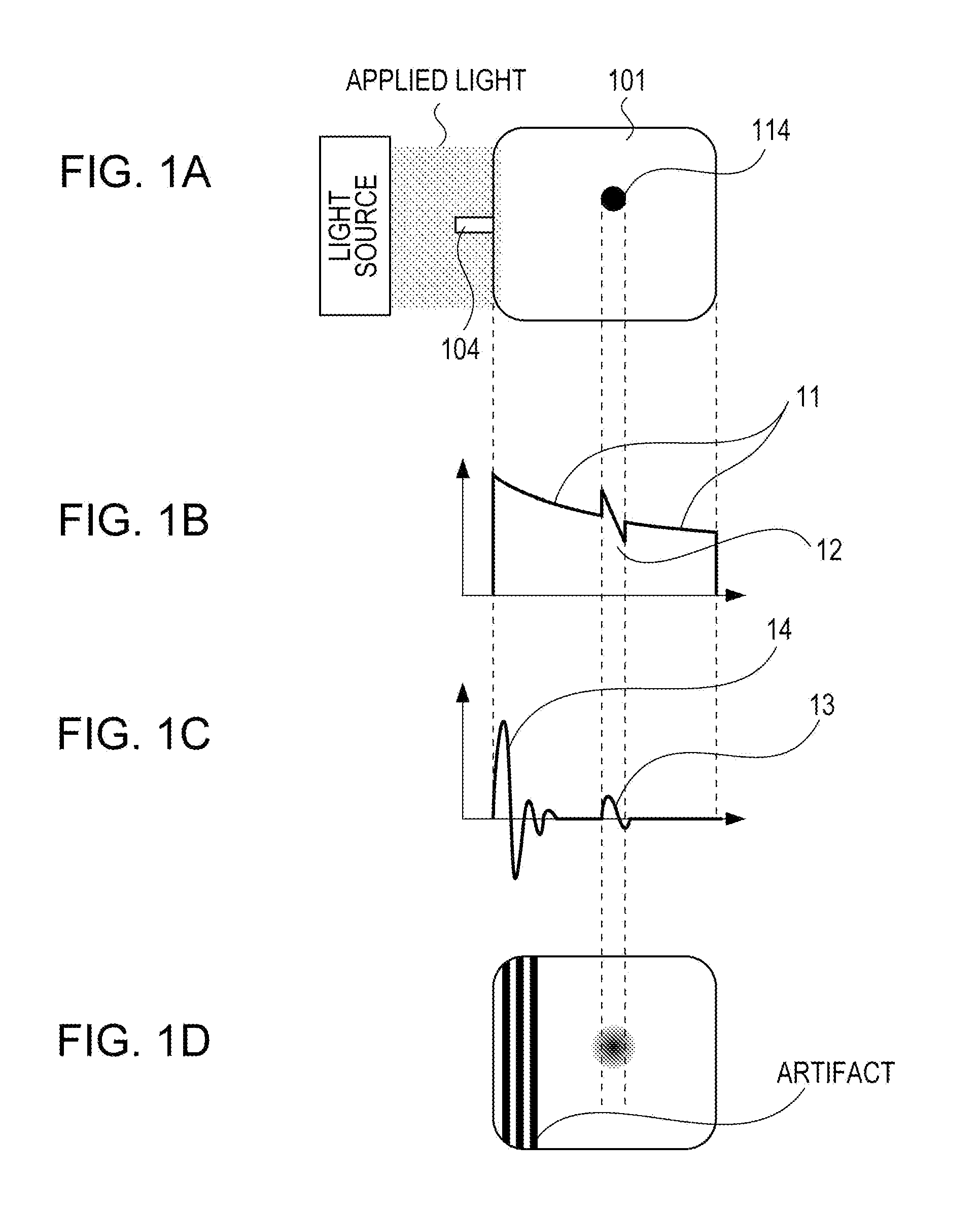
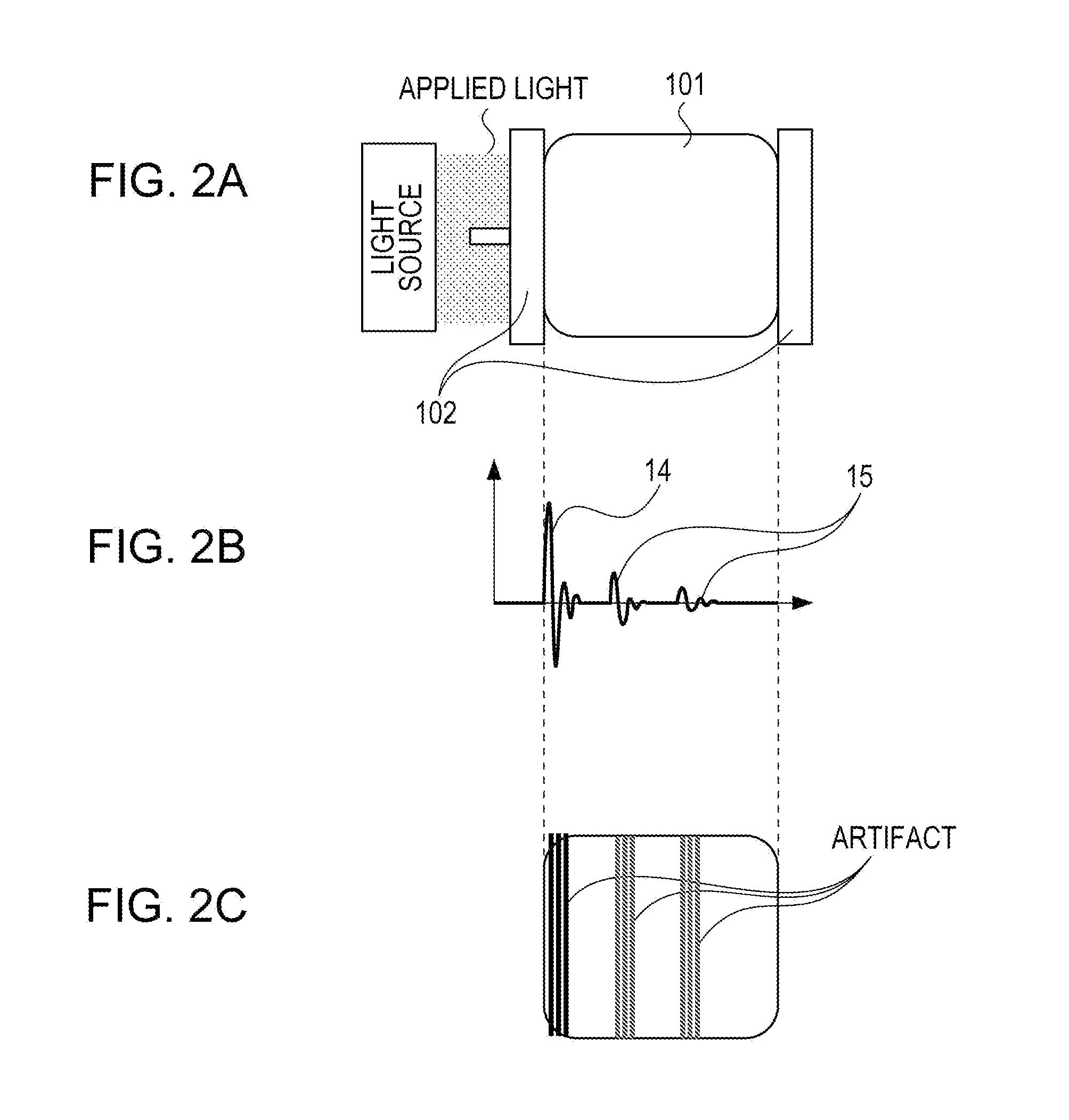
[0032]FIG. 3 schematically illustrates a photoacoustic imaging apparatus according to the first embodiment of the present invention. In the photoacoustic imaging apparatus, a light source emits light (pulsed light) and the specimen 101 is irradiated with the light, indicated at 115, through an irradiating unit 103. A light absorber (e.g., tumor to be detected) in the specimen 101 absorbs light energy, thus generating an acoustic wave. The generated acoustic wave is propagated through the specimen and then reaches the acoustic wave detecting...

example 1

[0051]An example in which image data was actually generated according to an application of the first embodiment will be described below. FIG. 6 schematically illustrates a photoacoustic imaging apparatus used. A Nd:YAG laser generating pulsed light of approximately 10 nanoseconds (FWHM) and having a wavelength of 1064 nm was used as a light source. Plastic plates having a thickness of 10 mm were used as holding plates 602. A device array 603 included devices of lead zirconate titanate (PZT) arranged two-dimensionally. The number of devices was 18×18, the arrangement of devices was a square type (square matrix), and the pitch of devices was 2 mm. A signal processor 604 included an interfacial acoustic wave reducer 605 and an imaging unit 606 and was installed as a program on a computer. Signal flows in the signal processor 604 included a flow A and a flow B. In the flow A, received signals were supplied from the device array 603 to the interfacial acoustic wave reducer 605 and reduce...

second embodiment

[0056]A photoacoustic imaging apparatus according to a second embodiment further includes a scanning unit that scans acoustic wave detecting devices and a light-irradiated area (irradiating unit) relative to a specimen. In an adding step, received signals obtained by the same acoustic wave detecting device in different scan positions are added to obtain a summed signal for each acoustic wave detecting device. In a normalizing step, the summed signal is normalized for each scan position and for each acoustic wave detecting device to obtain a normalized signal. In a reducing step, a reduced signal for each acoustic wave detecting device in each scan position is obtained using the received signal and the normalized signal. Such processes can effectively reduce an amplitude caused by an interfacial acoustic wave and that caused by a reflected interfacial acoustic wave even when the spatial distribution of light intensity has a large difference in intensity.

[0057]The second embodiment wi...


PUM


Abstract

A photoacoustic imaging apparatus includes a signal processor. The signal processor includes an adding unit configured to add received signals obtained by acoustic wave detecting devices to obtain a summed signal, a normalizing unit configured to normalize the summed signal for each acoustic wave detecting device with reference to an amplitude value in the received signal in the acoustic wave detecting device at the time when a maximum amplitude value in the summed signal is obtained to obtain a normalized signal, a reducing unit configured to subtract the normalized signal from the received signal for each acoustic wave detecting device to obtain a reduced signal in which the amplitude value in the received signal at the time when the maximum amplitude value in the summed signal is obtained is reduced, and an imaging unit configured to generate image data using the reduced signals.

Description

BACKGROUND OF THE INVENTION[0001]1. Field of the Invention[0002]The present invention relates to an apparatus and method for photoacoustic imaging, and in particular, relates to a technique for measuring optical characteristics of the interior of a specimen using the photoacoustic effect.[0003]2. Description of the Related Art[0004]One of photoacoustic imaging techniques is photoacoustic tomography (PAT). According to the PAT technique, a specimen, such as biological tissue, is irradiated with pulsed light emitted from a light source. A light absorber absorbs the light propagated and scattered in the specimen, thus generating an acoustic wave. Such an acoustic wave generating mechanism is called the photoacoustic effect. A light absorber, such as tumor, often has a higher light energy absorption coefficient than its peripheral tissue. Accordingly, the light absorber absorbs more light than the peripheral tissue and instantaneously expands. In a photoacoustic imaging apparatus utiliz...

Claims


Application Information

Patent Timeline
IPC IPC(8): G01N29/04
CPCA61B5/0095A61B5/4312G01N29/043G01N29/32G01N29/4463G01N33/4833G01N2291/023G01N2291/0289G01N2291/0423G01N2291/044
Inventor NANAUMI, RYUICHI
Owner CANON KK
Why Eureka
Try Eureka