Filter apparatus and filter plate system

a filter apparatus and filter plate technology, applied in the field of filter apparatuses and filter plate systems, can solve the problems of reducing the adhesion to the culture surface, reducing the viability of the colony, and/or reducing the maturity of the colony, so as to minimize the disturbance of aggregates and reduce the disturbance of culture media. , the effect of efficient and rapid replacement of culture media

Active Publication Date: 2011-09-29
STEMCELL TECHNOLOGIES
View PDF10 Cites 67 Cited by
  • Summary
  • Abstract
  • Description
  • Claims
  • Application Information

AI Technical Summary

Benefits of technology

[0042]Examples disclosed herein provide a device and method which allow for efficien

Problems solved by technology

However the size of the clumps being passaged contributes to the success of the colony, where clumps that are too large have an increased probability of spontaneous differentiation, and clumps that are too small may have reduced adhesion to the culture surface, reduced viability, and/or reduced colony maturity by the time of the next passage.
It is not possible to mechanically select aggregates of the correct size, and successful PSC culture relies on the practiced skill of the researcher in breaking up the colonies to the optimal size.
Keeping the aggregates at low density alleviates this problem somewhat, but cannot completely prevent the aggregates from coming into physical contact with one another.
Physically separating the aggregates into individual wells of a multi-well plate alleviates this problem, but is time consuming and inefficient.
Using gravity to separate cellular aggregates from the surrounding milieu of non-aggregated single cells, particulate matter, and liquids can be slow and inefficient.
Aggregates initially at the top of the tube will take

Method used


Image

  • Filter apparatus and filter plate system
  • Filter apparatus and filter plate system
  • Filter apparatus and filter plate system

Examples


example 1

Formation of Human ES Cell Aggregates by Forced Aggregation in Microwells

[0166]The following example used a microwell-textured plate (AggreWell™400 from Stemcell Technologies Inc., Vancouver, Canada, Catalogue #27845) for the forced aggregation of human embryonic stem (hES) cells in to embryoid bodies (EBs) of defined cell numbers.

[0167]Undifferentiated H1 hES cells were cultured to semi-confluency, using standard techniques. Typically, colonies reach semi-confluency 6 days after passaging of 2400 small clumps onto matrigel-coated 10-cm dishes and 7 mLs of mTeSR™1 media with daily media changes. An AggreWell™400 plate was removed from the packaging in a sterile tissue culture hood. Each of the 8 microwell-containing wells of the plate was rinsed with 1 mL of PBS, and the PBS was then removed by aspiration. 1 mL of medium was added to each well of the AggreWell™400 plate. Medium used in this example was AggreWell Medium™ (STEMCELL Technologies, Catalogue #27845). Y27632 Rock inhibito...

example 2

Separation of EBs from Single Cells Using Commercially Available Cell Strainer in Non-Standard Way

[0169]EBs were formed as described in Example 1, using AggreWell™400 from Stemcell Technologies Inc. Briefly, a single cell suspension containing 2.4×10⁶ H1 hES cells was added to each well of an AggreWell™400 plate, to generate approximately 1,200 EBs of 2,000 cells each. The EBs were then harvested as follows:

[0170]A cell strainer with 40 μm nylon mesh (Becton Dickson, Catalogue #352340) was removed from its packaging inside a sterile tissue culture hood and handled via its handle. The strainer was carefully placed upside down atop 50 ml test tube, as depicted in FIG. 12A. The cell strainer is not stably supported in this position, so a tight-fitting test tube rack was used to hold the 50 mL tube completely level and upright. Care was also taken throughout this procedure to avoid bumping the tube or the strainer, as it could easily fall off the tube. EBs were harvested from the AggreW...

example 3

Separation of EBs from Single Cells Using Filter Apparatus Prototype-1

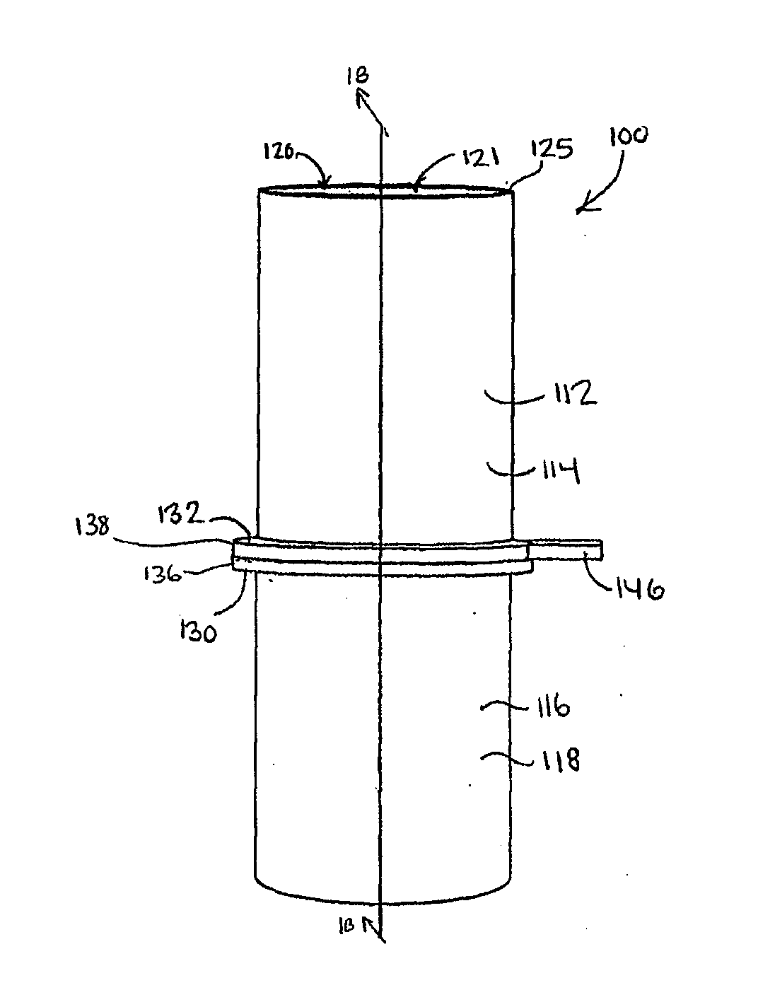
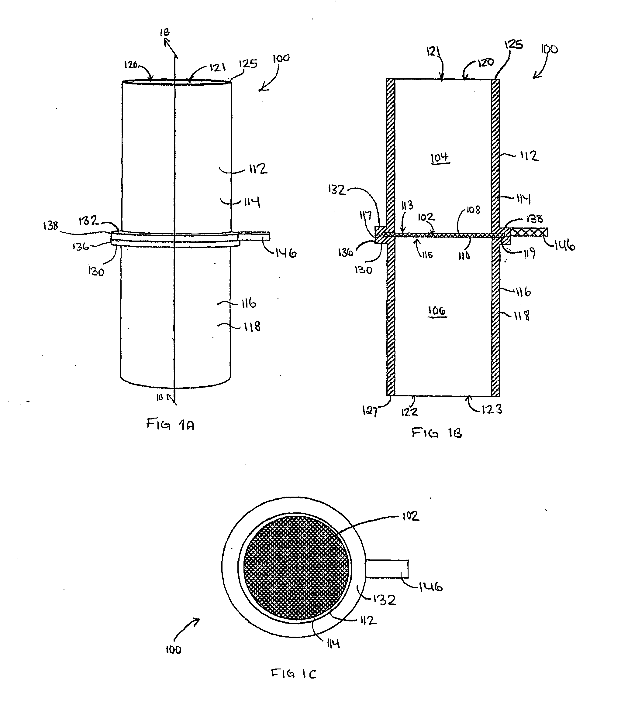
[0173]A filter apparatus as described hereinabove with respect to FIG. 1 was fashioned using the plastic casings from 2 commercially available cell strainers, and 50 μm nylon mesh. The cell strainers were disassembled, removing the mesh and side walls, leaving only the plastic casings. The plastic casings were placed with upper (flange) edges facing each other. A fresh piece of nylon mesh with 50 μm diameter openings (BioDesign Inc.) was placed between the two plastic casings, and the 3 parts were glued together. Excess nylon was trimmed from around the casings, resulting in the apparatus shown in FIG. 14. This device fit securely atop a 50 mL tube in either orientation.

[0174]Side walls were then fashioned onto the device using materials available in the lab such as tape and parafilm, to create a reservoir for application of cell suspension or washing solutions. The resulting device is shown in FIG. 15. This proto...


PUM

PropertyMeasurementUnit
Pore sizeaaaaaaaaaa
Pore sizeaaaaaaaaaa
Mesh sizeaaaaaaaaaa

Abstract

A filter apparatus comprises a filter having first and second opposed surfaces. A first reservoir is positioned adjacent with the first surface and in communication with the first surface, and a first inlet-outlet port is in communication with the first reservoir and spaced from the first surface. A second reservoir is positioned adjacent the second surface, and in communication with the second surface, and a second inlet-outlet port is in communication with the second reservoir and spaced from the second surface. A filter plate system comprises a reservoir plate. The reservoir plate comprises at least one reservoir well. The filter plate system further comprises a strainer plate. The strainer plate comprises at least one strainer well, which is removably receivable in the reservoir well. The strainer well comprises at least one mesh wall portion.

Description

CROSS-REFERENCES TO RELATED APPLICATIONS[0001]This application claims priority from U.S. Provisional Patent Application No. 61 / 139,074, filed on Dec. 19, 2008, which is incorporated herein by reference in its entirety.FIELD[0002]The specification relates to filter apparatuses and filter plate systems. Specifically, the specification relates to filter apparatuses usable to separate and collect cellular material from a liquid, and filter plate systems usable in cell culture systems.INTRODUCTION[0003]The following is not an admission that anything discussed below is prior art or part of the common general knowledge of persons skilled in the art.[0004]Many cell-based assays involve the formation of cellular aggregates, including 3D spheroids.[0005]The usefulness of three-dimensional spheroid culture systems has been embraced in multiple fields of study [reviewed in Edelman & Keefer, Exp Neurol 192: 1-6 (2005)].[0006]Neural stem cell biology commonly employs 3-D spheroids known as neuros...

Claims


Application Information

Patent Timeline
IPC IPC(8): B01D35/28B01D39/08B01D39/10B01D37/00B01D35/30
CPCC12M47/02B01D39/1692B01D35/30B01D2201/30G01N1/34G01N1/405G01N1/4077G01N2001/4088
Inventor ANTONCHUK, JENNIFERMILLER, CINDY
Owner STEMCELL TECHNOLOGIES
Why Eureka
Try Eureka