Method of molding a hollow body of revolution

a technology of hollow body and revolution, which is applied in the direction of manufacturing tools, single-unit apparatuses, instruments, etc., can solve the problems of spoiling the appearance of parts and harming the quality image of parts

Inactive Publication Date: 2011-09-29
APTAR FRANCE SAS
View PDF5 Cites 17 Cited by
  • Summary
  • Abstract
  • Description
  • Claims
  • Application Information

AI Technical Summary

Benefits of technology

[0012]The core of the present invention lies in injecting the molten plastics material (containing solid particles that have reflective facets)...

Problems solved by technology

The junction or weld line is often visible to the final user, and spoils the appearance of the part.
The solid particles become concentrated along the junction li...

Method used


Image

  • Method of molding a hollow body of revolution
  • Method of molding a hollow body of revolution
  • Method of molding a hollow body of revolution

Examples


Embodiment Construction

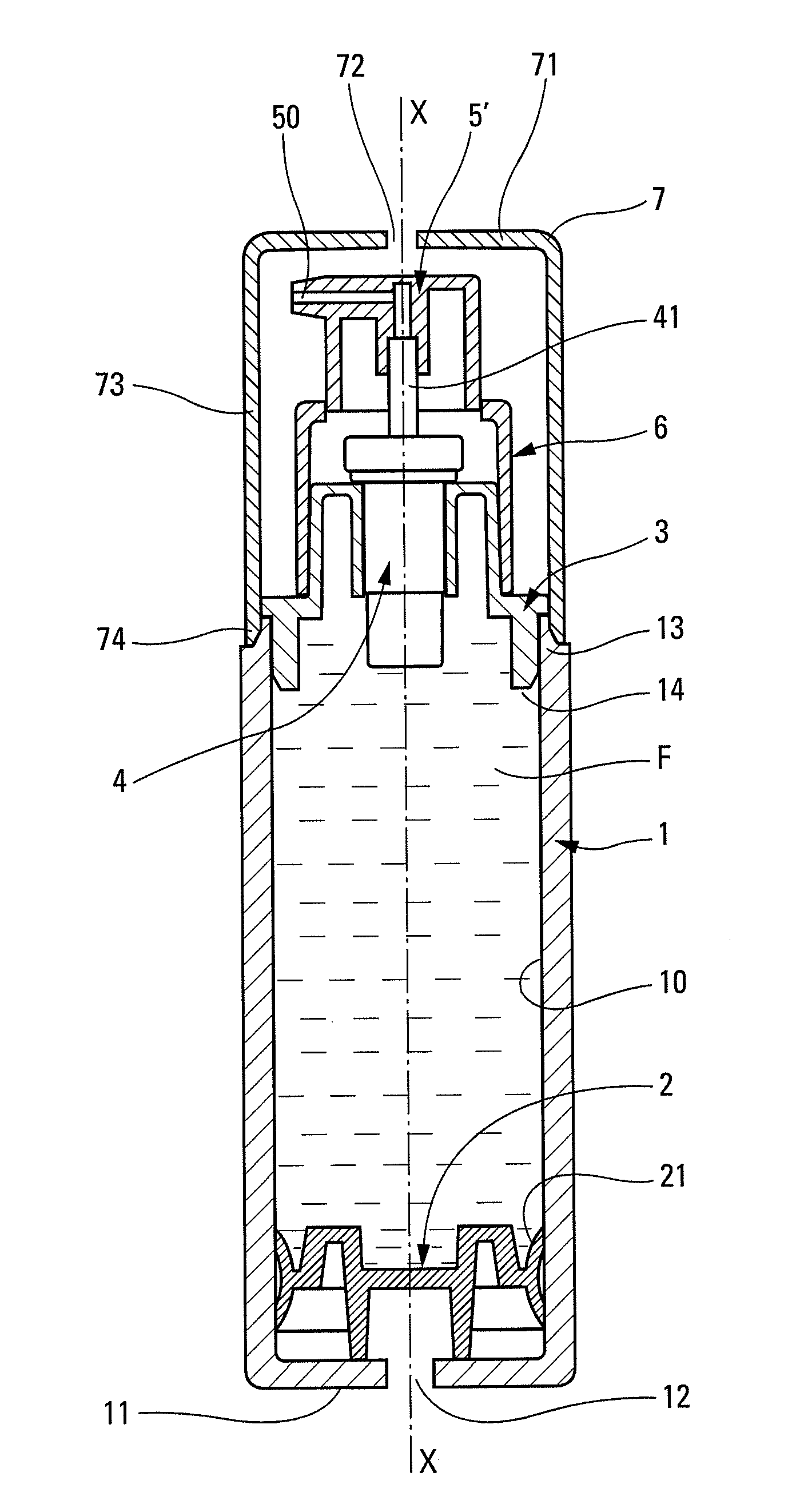
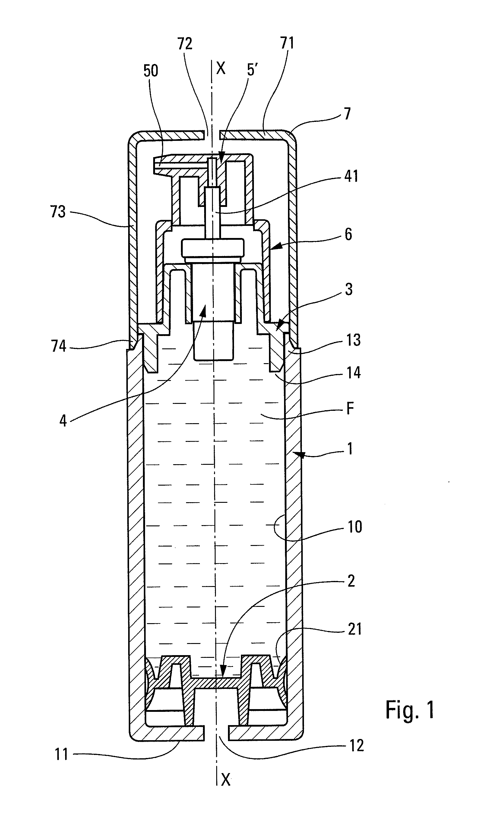
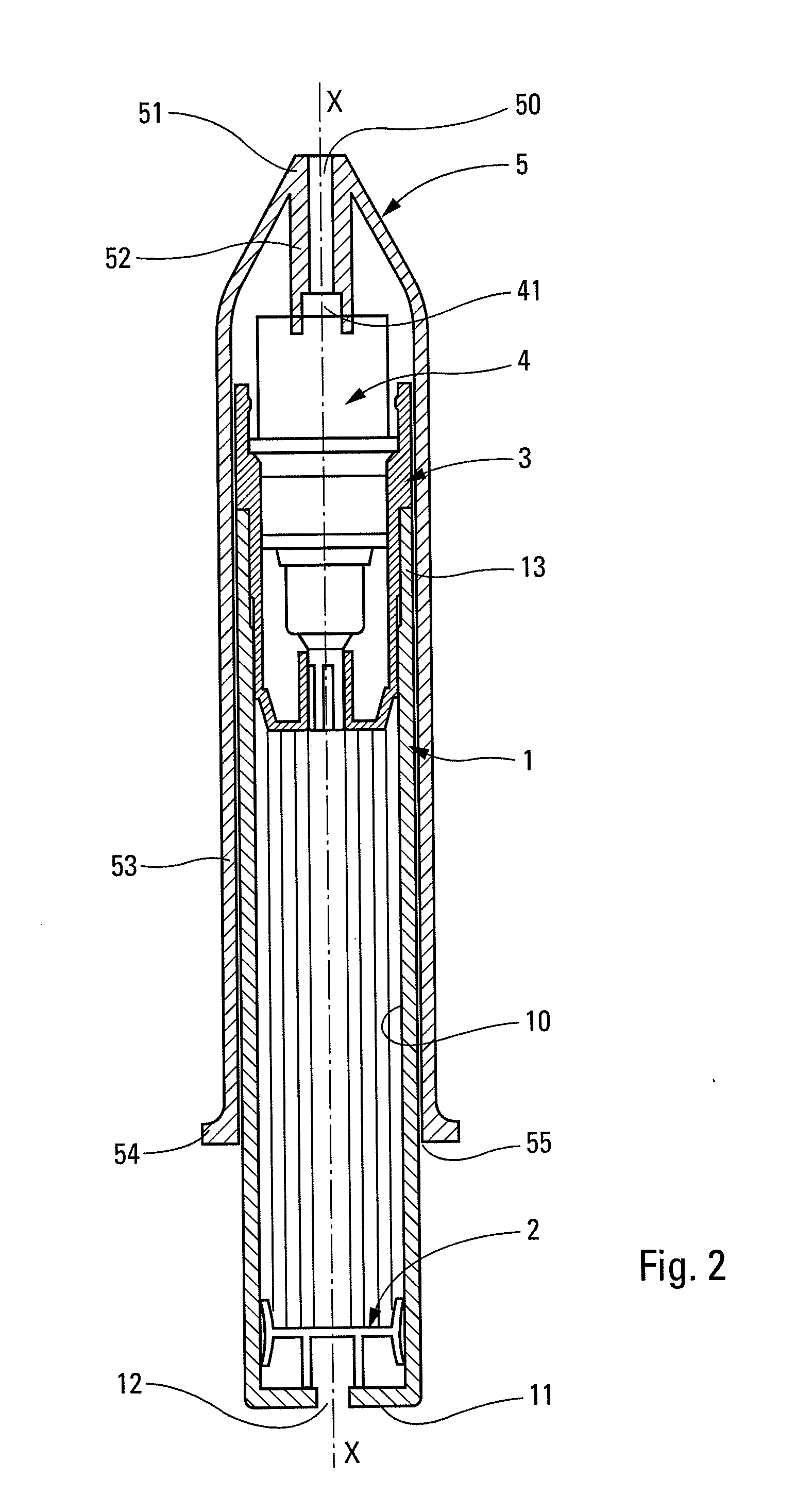
[0019]Reference is made initially to FIG. 1 while describing in detail a fluid dispenser incorporating component parts molded by the method of the invention. The dispenser presents an overall configuration that is generally symmetrical about an axis of revolution X. The dispenser comprises a reservoir 1 with a bottom 11 having a vent hole 12. On the inside, the reservoir 1 defines a sliding cylinder 10 of circularly cylindrical shape. The reservoir 1 contains a follower piston 2 having one or two sealing lips 21 for sliding in leaktight manner inside the cylinder 10. The fluid F is situated inside the cylinder 10 above the follower piston 2, which piston communicates with the outside air through the vent hole 12 such that it is constantly subjected to atmospheric pressure on its bottom face. It may be observed that the vent hole 12 is situated on the longitudinal axis of symmetry X of the dispenser. At its top end, the reservoir has a neck 13 defining an opening 14. The fluid reserv...


PUM


Abstract

A method of molding by injecting plastics material into a mold to make a part that is symmetrical about an axis of revolution, the part being hollow with a through passage along the axis, the part having two axial ends each defining an annular opening, the method comprising injecting the plastics material into the mold via an annular opening in an axial end of the part along an annular injection line, the plastics material containing solid particles of the flake or pearlescent type, thereby imparting flake and/or pearlescent highlights to the molded part.

Description

FIELD OF THE INVENTION[0001]The present invention relates to a method of injection molding molten plastics material into a mold in order to make a part that is hollow with a through passage. Preferably, the part is symmetrical about an axis of revolution so as to define two axial ends, each defining an axial opening. Such parts may be used in numerous technical fields, and more particularly in the fields of cosmetics, perfumery, or indeed pharmacy, being in the form of a reservoir, a fastener ring, a decorative bushing, or a pusher and a protective cap.BACKGROUND OF THE INVENTION[0002]In conventional manner, parts are made by injection-molding plastics material into a mold that forms a mold cavity for filling with the molten plastics material. The mold cavity is fed with plastics material via an injection point that, by definition, presents a spot of very small size. The injection point defines the point where the molding is separated from the injection pipe on leaving the mold, and...

Claims


Application Information

Patent Timeline
IPC IPC(8): B29C45/18G01F11/00
CPCB05B11/0013B05B11/0048Y10T16/05B29C45/2708B29C2045/2714B29C45/261B05B11/028
Inventor ALATERRE, MICHELBAILLIE, MICKAEL
Owner APTAR FRANCE SAS
Why Eureka
Try Eureka