Solid state lighting using light transmissive solid in or forming optical integrating volume

a solid state, light transmissive technology, applied in the direction of lighting and heating apparatus, semiconductor devices of light sources, light source combinations, etc., can solve the problems of reducing the efficiency of lighting apparatus over time, reducing the efficiency of reflection, etc., to improve the efficiency of light extraction from the emitter package, reduce reflection efficiency, and reduce the effect of efficiency of reflection

Active Publication Date: 2011-09-29
ABL IP HLDG
View PDF3 Cites 11 Cited by
  • Summary
  • Abstract
  • Description
  • Claims
  • Application Information

AI Technical Summary

Benefits of technology

The solid material effectively fills the light integrating volume. Optically, the volume is analogous to an optical integrating cavity. However, the presence of the solid prevents entry or dirt or debris, which might otherwise contaminate the diffuse reflector and reduce efficiency of reflection and thus reduce efficiency of the lighting apparatus over time.
Often, the material of each solid state light emitter has a high index of refraction in the vicinity of the light emitting region of the solid state device, e.g. the material encapsulating the light emitting portion of the LED chip. In several of the examples, the light transmissive solid has an index of refraction higher than an index of refraction of an ambient environment in the region or area of the general lighting application, although it may be somewhat less than that of the material used in or with the solid state emitters. The close conformity of the light emitter interface region of the solid, with the light emitting region of the solid state light emitter, provides improved efficiency of light extraction from the emitter package, by effectively reducing total internal reflection within the emitter package.
In some examples, the coupling between the transmissive solid and the emitter is provided with an optical adhesive between the interface of the transmissive solid and the light emitting region of the solid state light emitter to substantially eliminate any air gap. Depending on the type of solid material used, it may also be possible to mold the solid directly over the light emitting region of the solid state light emitter, to avoid creation of an air gap. Either approach provides a coupling at the interface region that is relatively free of low index of refraction air and thus reduces internal reflections inside the emitter package and improves light extraction efficiency.
The ambient environment outside the apparatus, e.g. air or water at the emission surface, exhibits a low index of refraction. In the examples in which the transmissive solid has an index of refraction higher than the ambient environment, the light emission surface of the transmissive solid tends to exhibit total internal reflection with respect to light reaching that surface from within the transmissive solid at relatively small angles of incidence with respect to that surface. In some examples, it is possible to utilize this total internal reflection to advantage to reduce the size of the mask or otherwise enlarge the effective aperture (size of the optical passage) through which light emerges from the integrating volume. As with the mask, light that is reflected back from the surface will be reflected by the diffuse reflector and typically will subsequently pass out through the exposed light emission surface (due to larger incident angle). Due to the larger optical aperture or passage, the apparatus can actually emit more light with fewer average reflections within the integrating volume, improving efficiency of the apparatus, yet still provide effective optical integration of light within the integrating volume.
A relatively small mask, for example, having a reflective surface covering a portion of the light emission surface of the light transmissive solid in proximity to the solid state light emitters, can reflect light that otherwise would impact the surface at too steep an angle for total internal reflection at the surface. The combination of the mask and the total internal reflection substantially prevents any direct emissions from the one or more solid state light emitters from emerging through the light emission surface of the light transmissive solid. However, the orientation of the emitter(s) tends to conform the emission pattern more closely to the shape of the diffusely reflective interior surface of the reflector and thereby avoid bright areas or “hot spots” on the reflective surface that might otherwise have been created by other orientations of the emitter(s).

Problems solved by technology

However, the presence of the solid prevents entry or dirt or debris, which might otherwise contaminate the diffuse reflector and reduce efficiency of reflection and thus reduce efficiency of the lighting apparatus over time.

Method used


Image

  • Solid state lighting using light transmissive solid in or forming optical integrating volume
  • Solid state lighting using light transmissive solid in or forming optical integrating volume
  • Solid state lighting using light transmissive solid in or forming optical integrating volume

Examples


Embodiment Construction

In the following detailed description, numerous specific details are set forth by way of examples in order to provide a thorough understanding of the relevant teachings. However, it should be apparent to those skilled in the art that the present teachings may be practiced without such details. In other instances, well known methods, procedures, components, and circuitry have been described at a relatively high-level, without detail, in order to avoid unnecessarily obscuring aspects of the present teachings. Generally, the illustrations in the figures are not drawn to scale, but instead are sized to conveniently show various points under discussion herein.

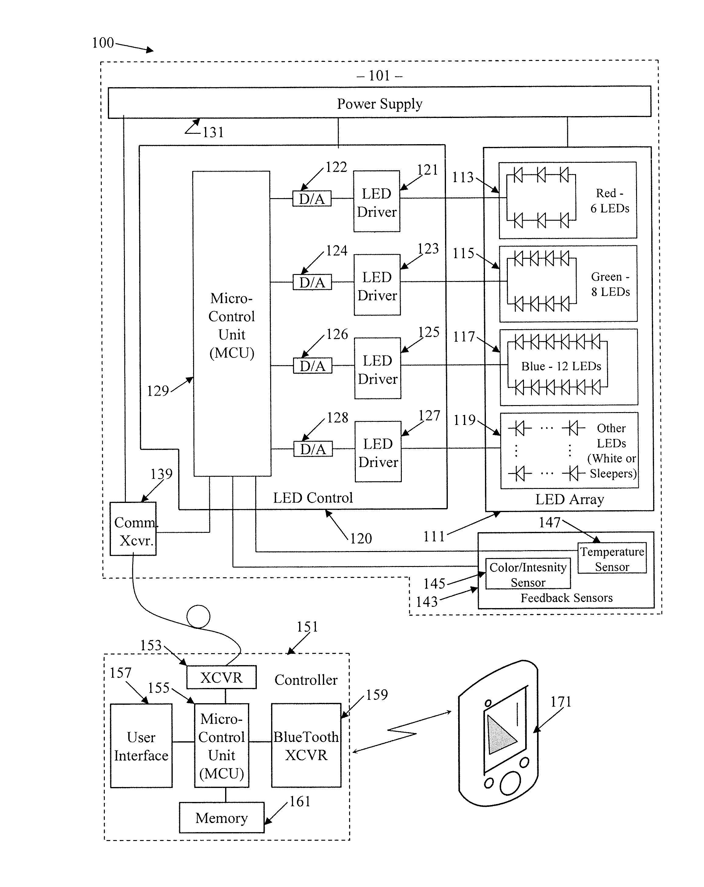
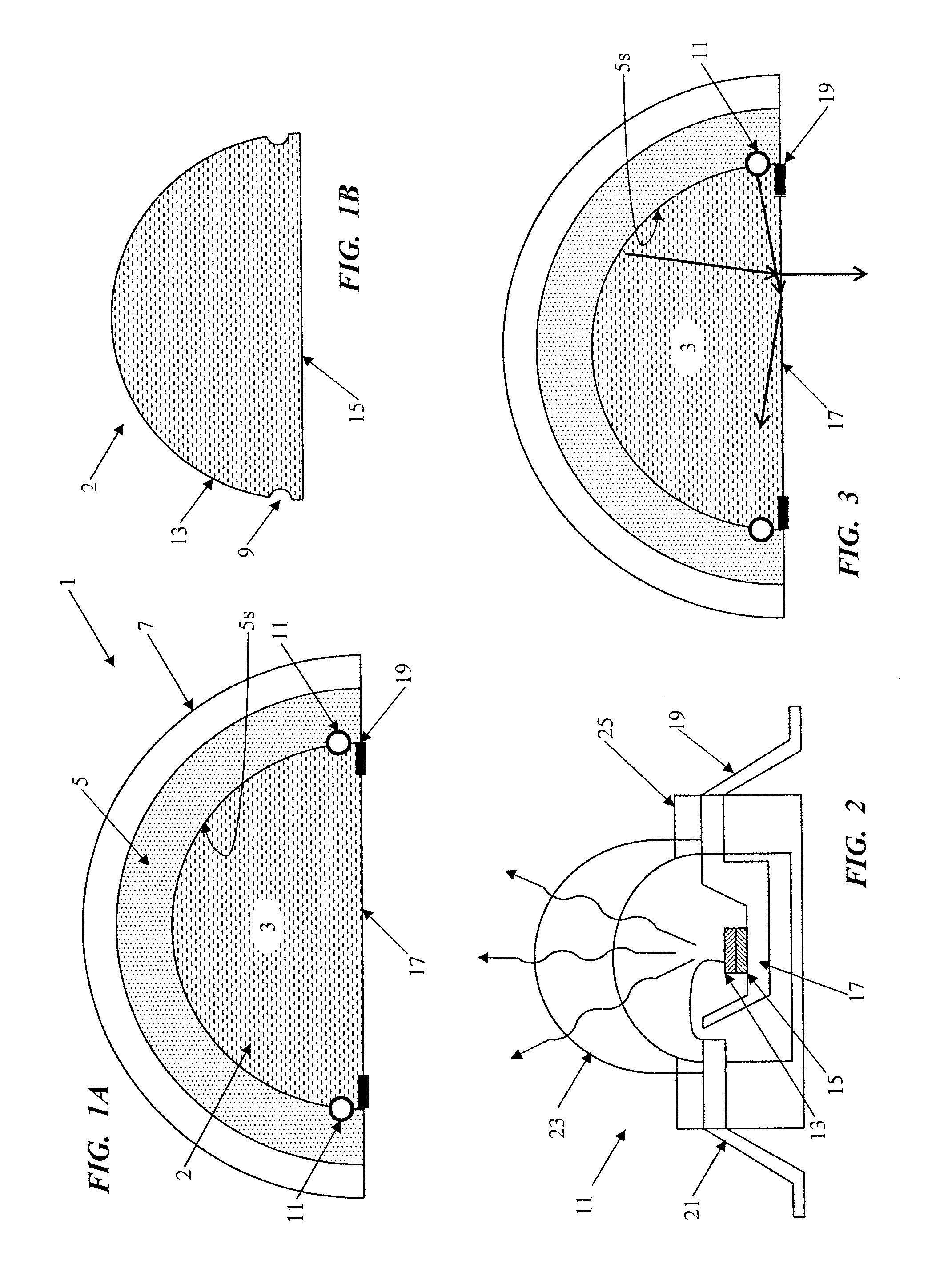
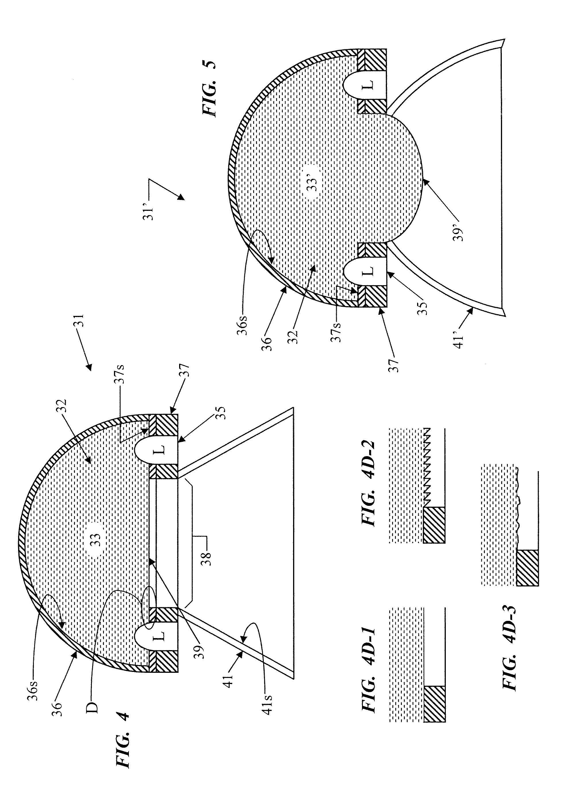
The various examples discussed below relate to lighting fixtures or apparatuses using solid state light sources and / or to lighting systems incorporating such devices, in which at least a substantial portion of an optical integrating volume is filled with a light transmissive solid. Techniques for manufacturing certain elements of th...


PUM


Abstract

An exemplary general lighting fixture includes an assembly forming an optical integrating volume for receiving and optically integrating light from one or more solid state light emitters and for emitting integrated light. The assembly includes a reflector having a diffusely reflective interior surface defining a substantial portion of a perimeter of the integrating volume. A light transmissive solid fills at least a substantial portion of the optical integrating volume. A light emitter interface region of the solid, for each solid state light emitter, closely conforms to the light emitting region of the respective emitter. A surface of the transmissive solid conforms closely to and is in proximity with the interior surface of the reflector. The transmissive solid also provides a light emission surface, at least a portion of which forms a transmissive optical passage for emission of integrated light, from the volume, in a direction facilitating a general lighting application.

Description

TECHNICAL FIELD The present subject matter relates to solid state type light fixtures each having an optical integrating volume filled with a solid light transmissive material, systems incorporating such light fixtures, as well as techniques for manufacturing and operating such equipment, for general lighting applications.BACKGROUND As costs of energy increase along with concerns about global warming due to consumption of fossil fuels to generate energy, there is an every increasing need for more efficient lighting technologies. These demands, coupled with rapid improvements in semiconductors and related manufacturing technologies, are driving a trend in the lighting industry toward the use of light emitting diodes (LEDs) or other solid state light sources to produce light for general lighting applications, as replacements for incandescent lighting and eventually as replacements for other older less efficient light sources.The actual solid state light sources, however, produce light...

Claims


Application Information

Patent Timeline
Patent Type & Authority Applications(United States)
IPC IPC(8): F21V7/22
CPCF21K9/00F21K9/54Y10S362/80F21Y2101/02F21Y2113/005F21V7/0008F21K9/62F21K9/68F21Y2113/13F21Y2115/10
Inventor RAMER, DAVID P.RAINS, JR., JACK C.
Owner ABL IP HLDG
Why Eureka
Try Eureka