Oscillating piston engine

a piston engine and oscillating piston technology, applied in the direction of combustion engines, engines with oscillating pistons, machines/engines, etc., can solve the problems of large volume requirements, large mass to energy ratio, low efficiency of conventional engines, etc., and achieve the effect of reducing the number of rpms

Inactive Publication Date: 2011-10-06
CUNNINGHAM STEPHEN LEE +1
View PDF7 Cites 18 Cited by
  • Summary
  • Abstract
  • Description
  • Claims
  • Application Information

AI Technical Summary

Benefits of technology

[0013]Further provided is an option for the above engine, where one of the disks can be fixed to the housing so that it does not oscillate, and thus need not be connected to the crankshaft.

Problems solved by technology

However, conventional engines tend to have relatively low efficiencies, large mass to energy ratios, and relatively large volume requirements, any of which where improvement is highly desirable.
Furthermore, conventional engines tend to require relatively high RPMs to develop sufficiently high torque.
However, such a solution has the problem of localized high temperature spots and the strength of materials to transfer the high torque to the drive shaft.
Such engines have the problem of a large spinning toroidal chamber with electrical slip rings needed to carry the spark plug currents and a heavy Scotch yoke configuration to transfer the torque to the crank shaft.

Method used


Image

  • Oscillating piston engine
  • Oscillating piston engine
  • Oscillating piston engine

Examples


example configurations

[0076]With the above set of choices for the nine options, the embodiment of the engine used as the specific example shown in FIGS. 1-31 can be summarized as follows: It is a two cycle engine with 12 pistons, each piston is about 1.8 cm in diameter, they are mounted on the perimeter of a disk of about 5 cm radius, each piston has a thickness of about 18 degrees of arc. The transmission is comprised of 3 crank shafts connected to a center main shaft through gears with a ratio of about 1.485. The outer dimension of the engine is a little over 6 inches (about the size of a 2 pound coffee can), and the engine generates more than 10 horsepower at 5000 rpm (which is a relatively slow rotational speed for an engine of this size).

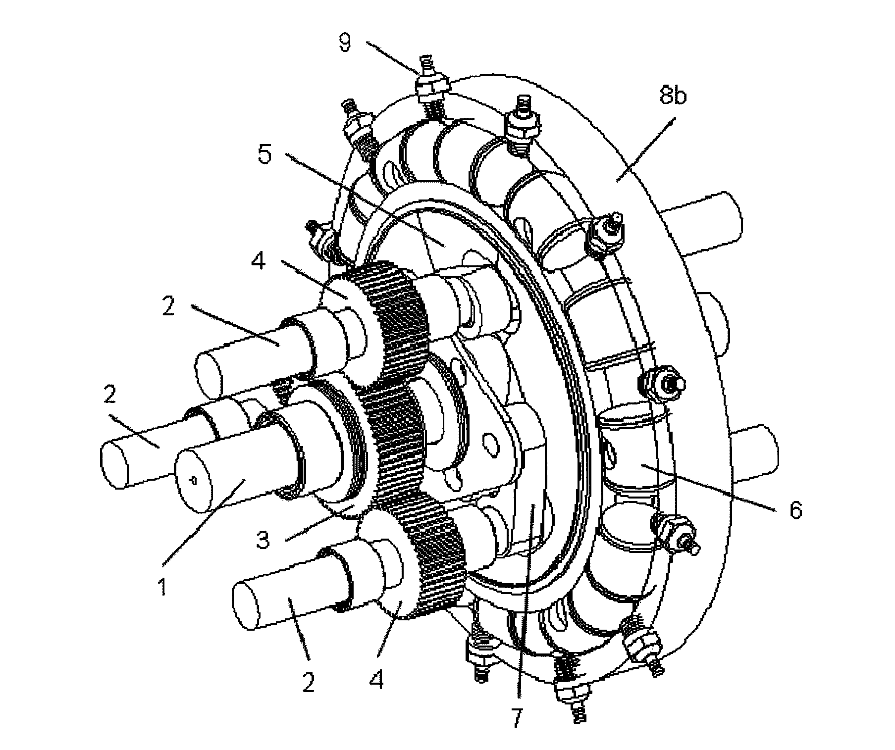
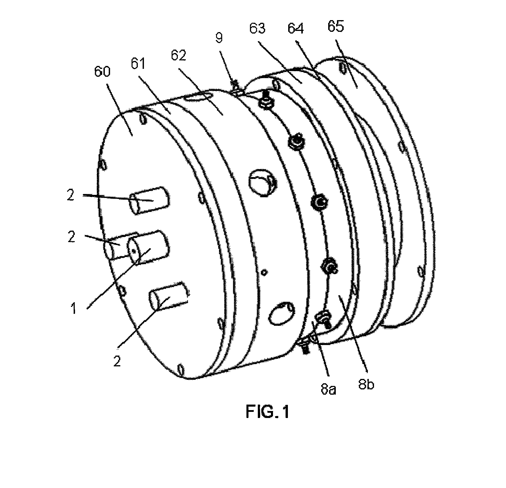
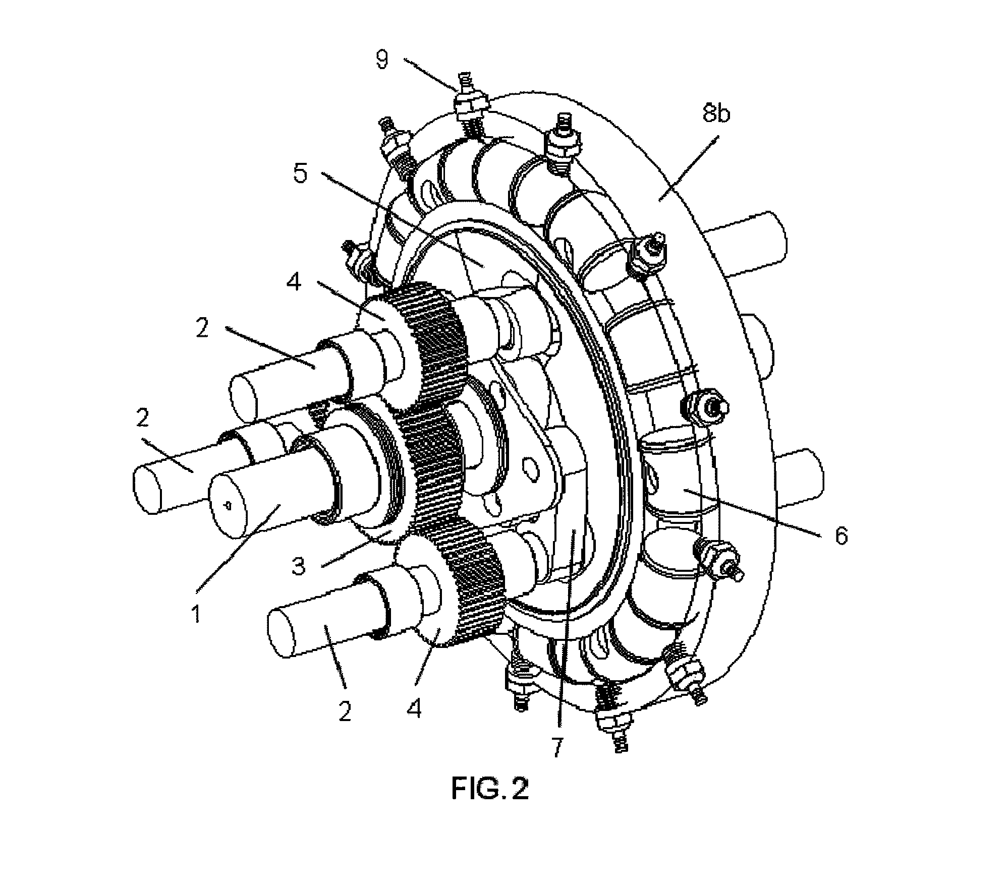
[0077]FIG. 1 shows an external view of the main part of the engine. Protruding from one end are the main shaft 1 and three crank shafts 2. Central to the motor are two halves of the toroidal combustion chamber, 8a and 8b, which contain twelve glow plugs 9 (or spark ...


PUM


Abstract

An engine configuration that places multiple pistons on one or two oscillating discs. The engine can be configured to operate as an internal combustion engine that uses diesel fuel, gasoline, or natural gas, or it can be configured as an expander to convert high pressure high temperature gas to rotary power. For any given set of choices of numbers of pistons and sizes of pistons, disks, and gears, there are disclosed dimensional constraints useful for more efficient functioning of the engine. This engine is especially suited as a driver for electrical power generation as it delivers high torque at low engine speeds, among other uses. Its compact design results in high power to weight ratios.

Description

CROSS-REFERENCES TO RELATED APPLICATIONS[0001]This application claims the benefit of U.S. provisional application Ser. No. 61 / 282,774 that was filed on Mar. 30, 2010, and is incorporated herein by reference.FIELD OF THE INVENTION[0002]This invention relates generally to the field of internal combustion engines, and this invention also relates to high pressure gas expanders. More specifically, this invention relates to the conversion of energy from one form (either chemical energy from the combustion of a variety of petroleum products or energy in the form of a high pressure gas) into rotational mechanical energy using an oscillating disk methodology. The rotational mechanical energy can be used to drive a generator to create electricity or drive a transmission in a moving vehicle (car, truck, plane, or boat).BACKGROUND OF THE INVENTION[0003]The conventional internal combustion engines use pistons that move in a linear back and forth motion. This motion is transferred to a rotating c...

Claims


Application Information

Patent Timeline
Patent Type & Authority Applications(United States)
IPC IPC(8): F02B53/00
CPCF01C9/002Y02T10/17F02B55/16F01C21/08F02B53/02Y02T10/12F02B53/14F02B2730/01
Inventor CUNNINGHAM, STEPHEN LEESTUART, MARTIN A.
Owner CUNNINGHAM STEPHEN LEE
Why Eureka
Try Eureka