Method of forming a joint

a joint and joint technology, applied in the field of joints, can solve the problem of having to be larger of the composite componen

Active Publication Date: 2011-10-06
AIRBUS OPERATIONS LTD
View PDF5 Cites 32 Cited by
  • Summary
  • Abstract
  • Description
  • Claims
  • Application Information

AI Technical Summary

Benefits of technology

[0012]By adapting the welding interface element to the thickness and shape of the two components, measurement and detailed manufacturing of bespoke parts is no longer required. The pointed prongs provide a high peel strength joint between the welding interface element and the first component.
[0019]The prongs may have a simple triangular or conical profile, or at least one of the prongs may have a transverse cross-sectional area which increases from the tip of the prong to form a pointed head, and then decreases to form an undercut face. The prongs may push aside fibres as they pierce the fibre layer(s), and then the fibres spring back behind the undercut face. The undercut face can thus increase the pull-through strength of the joint. Alternatively the prongs may cut the fibres as they pierce the fibre layers.
[0024]the amount of wastage of material in the fabrication process is minimized;
[0029]unconsolidated parts of each bed can support successive beds, enabling relatively complex shapes to be formed.

Problems solved by technology

This results in the composite component having to be larger than would otherwise be necessary to take into account the weak points introduced by the fastener holes.

Method used


Image

  • Method of forming a joint
  • Method of forming a joint
  • Method of forming a joint

Examples


Embodiment Construction

)

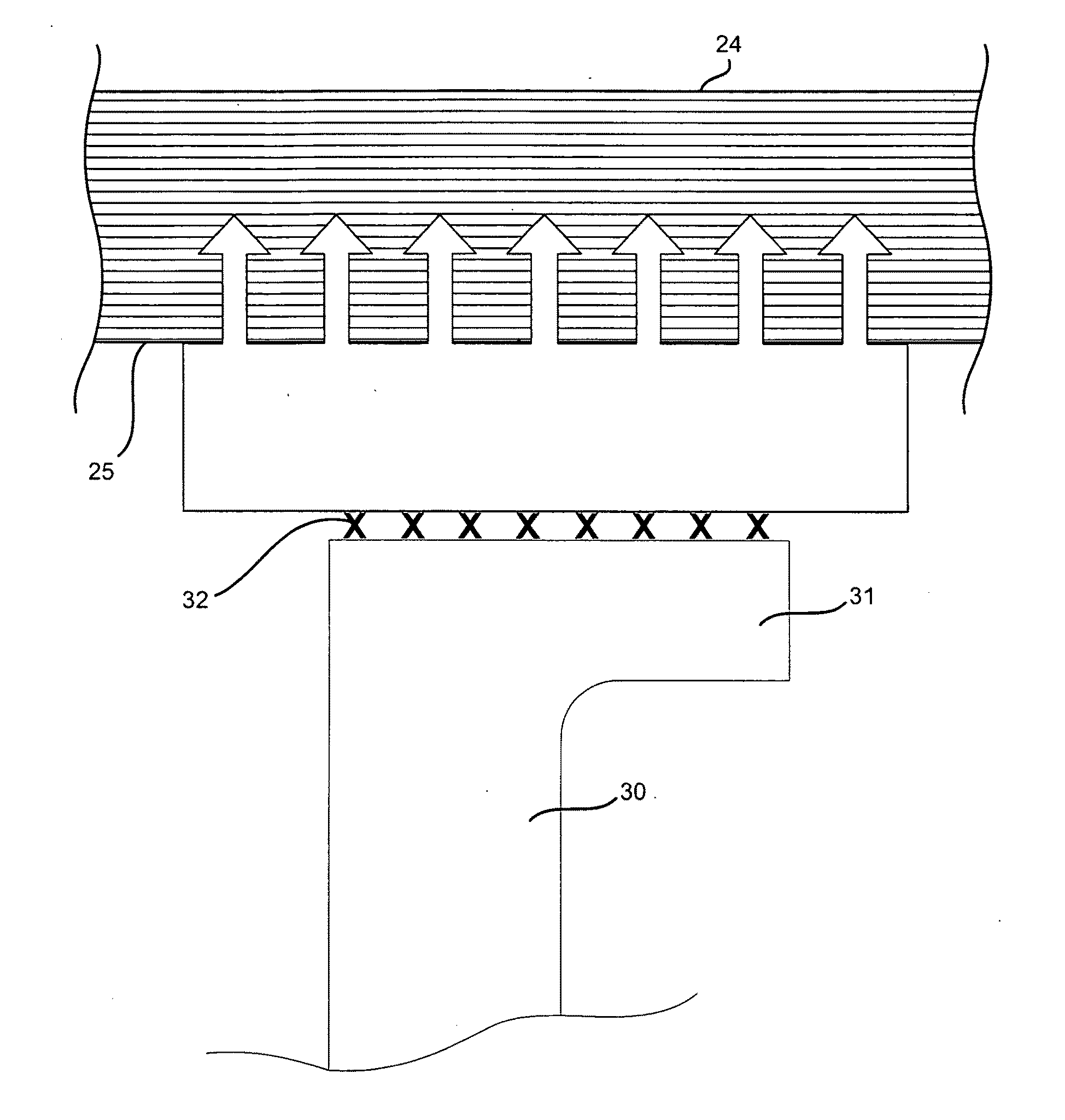
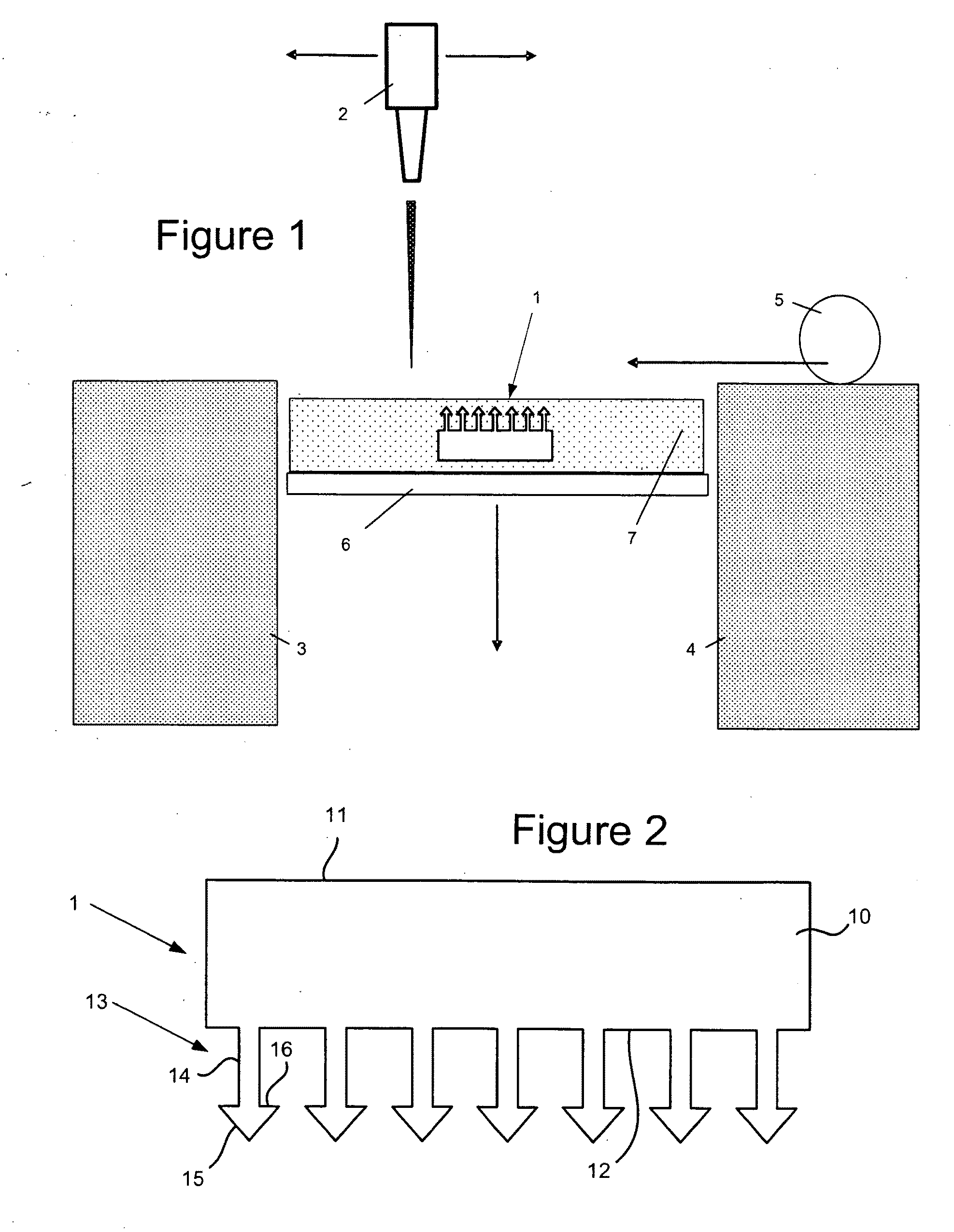
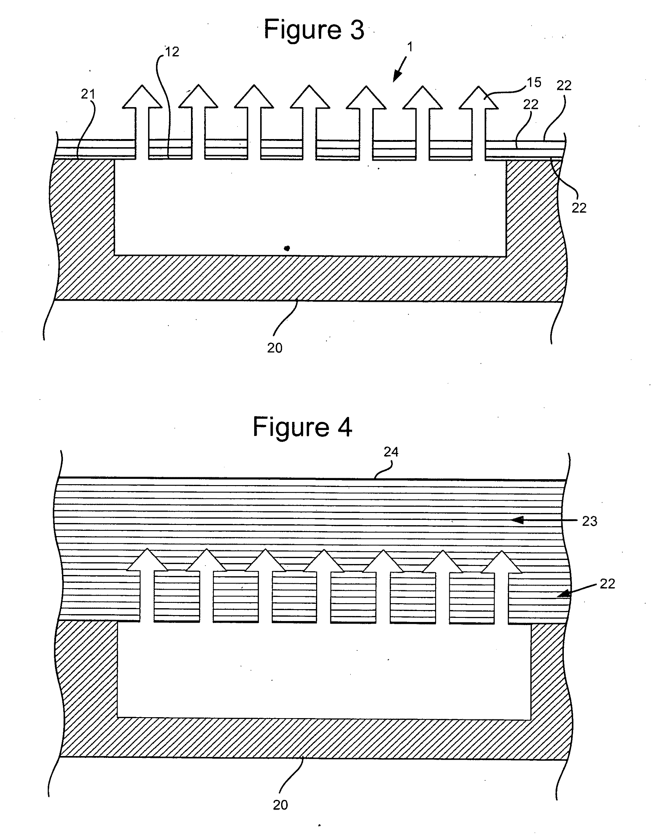
[0044]A method of forming a joint between a rib and a wing skin is shown in FIGS. 1-5. A welding interface element 1 is first manufactured by the powder-bed system illustrated in FIG. 1. The element 1 is formed by scanning a laser head 2 laterally across a powder bed and directing the laser to selected parts of the powder bed. More specifically, the system comprises a pair of feed containers 3, 4 containing powdered thermoplastic material such as polyetheretherketone (PEEK) or polyphenyline sulphide (PPS). A roller 5 picks up powder from one of the feed containers (in the example of FIG. 1, the roller 5 is picking up powder from the right hand feed container 4) and rolls a continuous bed of powder over a support member 6. The laser head 2 then scans over the powder bed, and a laser beam from the head is turned on and off to melt the powder in a desired pattern. Movement of the laser head 2 and modulation of the laser beam is determined by a Computer Aided Design (CAD) model of the ...


PUM

PropertyMeasurementUnit
distanceaaaaaaaaaa
energyaaaaaaaaaa
thermoplasticaaaaaaaaaa

Abstract

A method of forming a joint between a first component and a second component, the first component comprising a plurality of layers of fibres impregnated with a thermosetting matrix. A welding interface element is provided with an array of pointed prongs. One or more of the layers of fibres are penetrated with the prongs, either before or after the fibres have been impregnated with the thermosetting matrix. The first component is cured by heating the thermosetting matrix after the prongs have been embedded. A thermoplastic weld is formed between the second component and the welding interface element.

Description

FIELD OF THE INVENTION[0001]The present invention relates to a joint, and to a method of forming a joint between a first component and a second component, the first component comprising a plurality of layers of fibres impregnated with a thermosetting matrix.BACKGROUND OF THE INVENTION[0002]Joints with a thermosetting composite component are conventionally formed by fasteners such as bolts and rivets. This results in the composite component having to be larger than would otherwise be necessary to take into account the weak points introduced by the fastener holes. Also, the components of the joint must be measured and / or manufactured with close tolerances so that they mate together precisely at the joint.SUMMARY OF THE INVENTION[0003]A first aspect of the invention provides a method of forming a joint between a first component and a second component, the first component comprising a plurality of layers of fibres impregnated with a thermosetting matrix, the method comprising:[0004]a. p...

Claims


Application Information

Patent Timeline
Patent Type & Authority Applications(United States)
IPC IPC(8): F16B11/00B32B37/06B05D3/06
CPCB29C65/08Y10T403/477B29C65/362B29C65/72B29C66/112B29C66/1122B29C66/116B29C66/131B29C66/30321B29C66/43441B29C66/52441B29C66/71B29C66/7212B29C66/72141B29C66/7392B29C66/7394B29C67/0077B29C70/30B29L2031/3085B64C2001/0072Y02T50/433B29C65/342Y10T156/10B29C66/474B29C65/3676B29C65/3696B29C65/3492B29C65/3424B29K2071/00B29K2081/04B29K2307/04B29K2063/00B29C65/3432B29C65/3632B29C65/3476B29C66/721B29C64/153B33Y30/00B33Y10/00B33Y80/00Y02T50/40
Inventor KORYA, CHETANSANDERSON, TIMOTHY
Owner AIRBUS OPERATIONS LTD
Why Eureka
Try Eureka