
Device and method for generating a plasma flow

Inactive Publication Date: 2011-10-06
ADVANCED MACHINES
View PDF5 Cites 3 Cited by
  • Summary
  • Abstract
  • Description
  • Claims
  • Application Information

AI Technical Summary

Benefits of technology

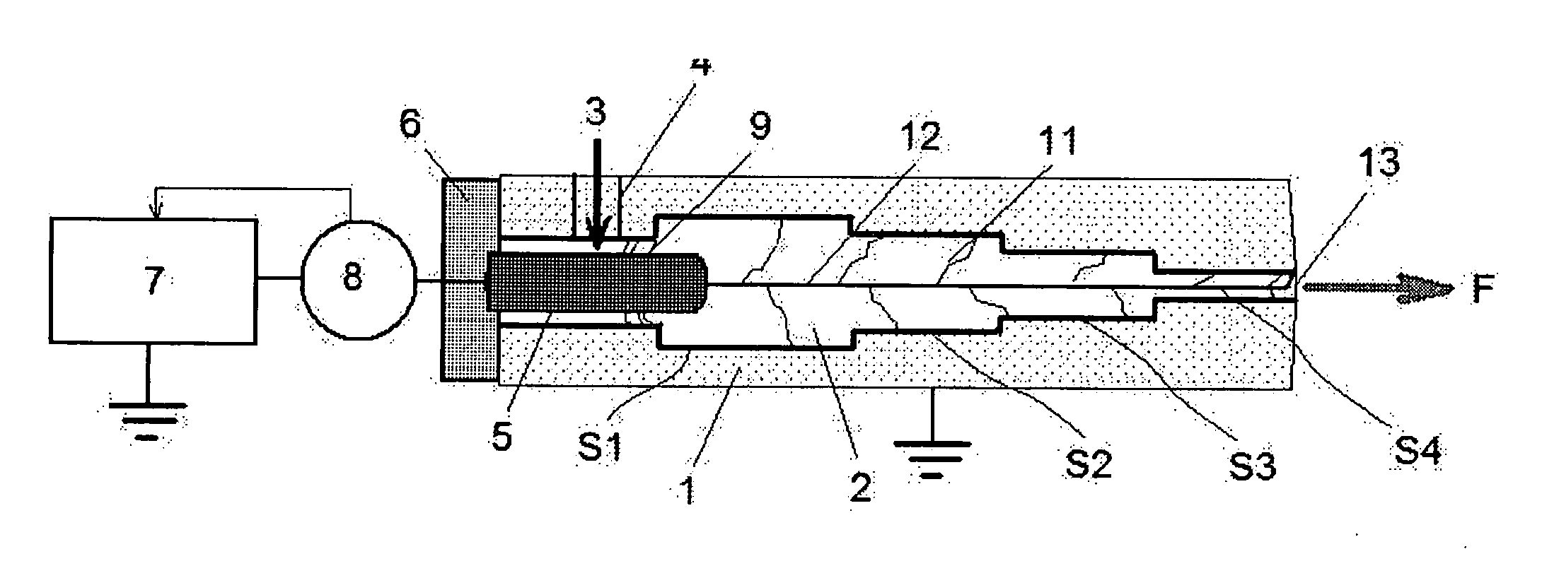
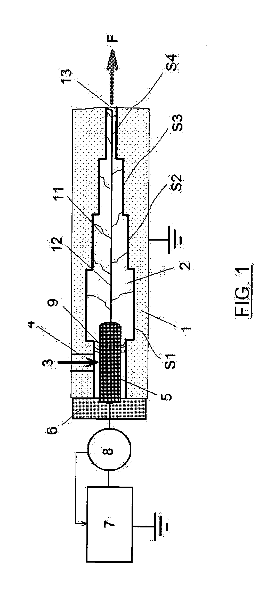
[0006]Configured in this way, the device according to the invention allows the limitation of the development of an electric arc inside a conductive housing to an end area positioned just before the opening of the housing intended to deliver the plasma flow on the workpiece to be treated. Indeed, the end area is configured in such a way as to develop an electric arc with the central electrode only starting from a certain minimum voltage. In this way, by applying a voltage lower than said minimum voltage, the electric arc is developed inside the central channel of the housing until approaching, or even reaching, said end area, then withdraws sharply in the direction of the central electrode. Subsequently, it resumes its development inside the channel in the direction of said end area until it withdraws again. In the end, this sequence of development and of withdrawal of the electric arc generates a relatively powerful plasma flow yet whose temperature is relatively low to allow its use in numerous surface treatment applications.
[0008]Configured in this way, the method according to the invention allows the creation of a sequence of phases of development and of phases of withdrawal of an electric arc inside the central channel of a conventional plasma nozzle so as to generate in the end a plasma flow having a low temperature and a relatively high power.

Problems solved by technology

However, in this state of the art, the plasma flow created has a very high temperature.
This plasma flow is not therefore suitable for the treatment of surfaces sensitive to heat such as plastic for example.

Method used


Image

  • Device and method for generating a plasma flow
  • Device and method for generating a plasma flow
  • Device and method for generating a plasma flow

Examples


example 1

[0029]This example uses the device of the invention in its configuration shown in FIG. 1.

[0030]Working Parameters:

Energy sourcedirect currentElectric voltage applied between3 kVthe electrode and the housingCarrier gasairFlow rate of the carrier gas60 l / minExternal pressureatmosphericDiameter of the central electrode3 mmDiameter of the central channel4 mmat the level of the ignition areaDiameter of section S18 mmDiameter of section S26 mmDiameter of section S34 mmDiameter of section S42 mmLength of each section35 mm

[0031]Result:[0032]A succession of development-withdrawal of an electric arc takes place between the central electrode and the section S4 at the frequency of 2 kHz.

example 2

[0033]This example uses the device of the invention in its configuration shown in FIG. 1.

[0034]Working Parameters:

Energy sourcedirect currentElectric voltage applied between the electrode2kVand the housingCarrier gasN2 / H2Flow rate of the carrier gas20 l / minExternal pressureatmosphericDiameter of the central electrode3 mmDiameter of the central channel at the level4 mmof the ignition areaDiameter of section S18 mmDiameter of section S26 mmDiameter of section S34 mmDiameter of section S42 mmLength of each section35 mm

[0035]Result:[0036]A succession of development-withdrawal of an electric arc takes place between the central electrode and the section S4 at the frequency of 1.5 kHz.

example 3

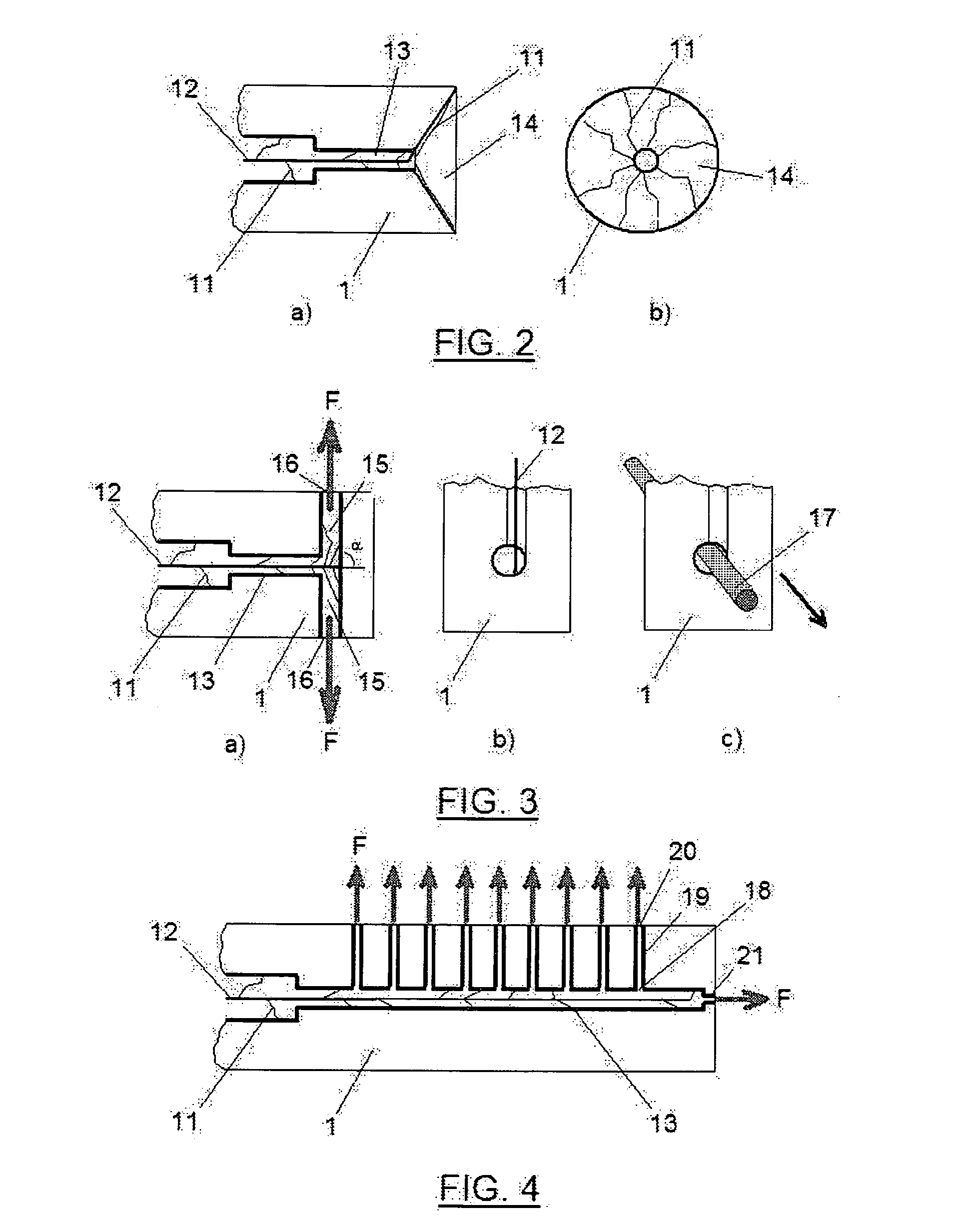
[0037]This example uses the device of the invention in its configuration shown in FIG. 2.

[0038]Working Parameters:

Energy sourcealternating currentat frequency of 22 kHzElectric voltage applied between3 kVthe electrode and the housingCarrier gasairExternal pressureatmosphericFlow rate of the carrier gas50 l / minDiameter of the central electrode3 mmDiameter of the central channel at the level4 mmof the ignition areaDiameter of section S18 mmDiameter of section S26 mmDiameter of section S34 mmDiameter of section S43 mmLength of each section10 mmDiameter of the end channel3 mmExternal diameter of the cone35 mm

[0039]Result:[0040]A succession of development-withdrawal of an electric arc takes place between the central electrode and the end of the cone at the frequency of 4 kHz.


PUM


Abstract

The invention relates to a device generating a plasma flow comprising an electrically conductive housing, tubular in shape, forming a central channel traversed by a vortex gas, a central electrode arranged coaxially in said channel and an electric power source intended to apply an electric voltage V between the electrode and the housing, characterised in that the mean diameter of the channel formed by the housing decreases progressively from an area situated substantially at the level of the free end of the electrode as far as an end area of said housing, said end area being configured in such a way that the minimum electric voltage Vcmin(0) to be applied in order to develop an electric arc between said electrode and said end area is strictly greater than said voltage V.

Description

TECHNICAL FIELD[0001]The present invention relates to a device and method for generating a plasma flow having a low temperature and a relatively high power.STATE OF THE ART[0002]In the area of surface treatment the use of a plasma flow is known so as to, among others, weld surfaces or cut surfaces. Such applications of a plasma flow have been described in particular in the U.S. Pat. No. 3,515,839. However, in this state of the art, the plasma flow created has a very high temperature. This plasma flow is not therefore suitable for the treatment of surfaces sensitive to heat such as plastic for example. The use is likewise known of a plasma flow for treating plastic surfaces so as to increase their wettability. Such an application has been described in particular in the article “Surface Treatment of Plastics by Plasmajet”, published in the Journal of the Adhesion Society of Japan, Volume 6, No. 4, 2 Aug. 1968. In this document, the plasma flow is generated by applying a voltage betwee...

Claims


Application Information

Patent Timeline
IPC IPC(8): H05H1/48H05H1/03B01J19/08
CPCH05H1/34H05H1/32H05H2001/3494H05H1/3494
Inventor BEGOUNOV, STANISLAVGOLOVIATINSKI, SERGEYTSVETKOVA, IOULIA
Owner ADVANCED MACHINES
Learn More