

Transfer-laminating member and production method thereof
Inactive Publication Date: 2005-06-23
CANON KK
View PDF7 Cites 13 Cited by
- Summary
- Abstract
- Description
- Claims
- Application Information
AI Technical Summary
Benefits of technology
[0009] It is therefore an object of the present invention to provide a laminating member having a release layer curable at a low temperature without need of any aging and having high solvent resistance.
[0019] In the present invention, a transfer-laminating treatment applicable to matting may become feasible at a low process cost by providing a release layer for forming irregularities as a layer composed of a combination of particular resins and having particular properties.
Problems solved by technology
However, the melamine resins are required to be crosslinked by drying at a high temperature of at least 140° C., and so there has been an inconvenience of causing deformation even when a heat-resistant base material has been used.
Although the isocyanate-curable urethane resins are crosslinked at about 100° C., they are not completely cured by drying under heat upon coating.
Method used
View moreImage
Smart ImageViewing Examples

Examples
example 1
[0034] One hundred parts by mass of SHC 900 (trade name, product of GE Toshiba Silicone Co., Ltd.; a mixed solution of a silicone resin, a melamine resin and an alkyd resin; solvent:metyl ethyl keton; solid content: 30%) were mixed with 3 parts by mass of Sylysia 256 (trade name, product of Fuji Silysia Chemical Co., Ltd.; silica gel; average particle diameter: 3.0 μm), and the resultant mixture was fully stirred to prepare a coating formulation for a release layer. The coating formulation for the release layer was applied on a polyethylene terephthalate film (film thickness: 25 μm) by a Wire bar so as to give a coating weight of 10 g / m2 and then dried at 100° C. for 1 minute to obtain a matt film.
Login to View More PUM
| Property | Measurement | Unit |
|---|---|---|
| Particle diameter | aaaaa | aaaaa |
| Particle diameter | aaaaa | aaaaa |
| Electrical resistance | aaaaa | aaaaa |
Abstract
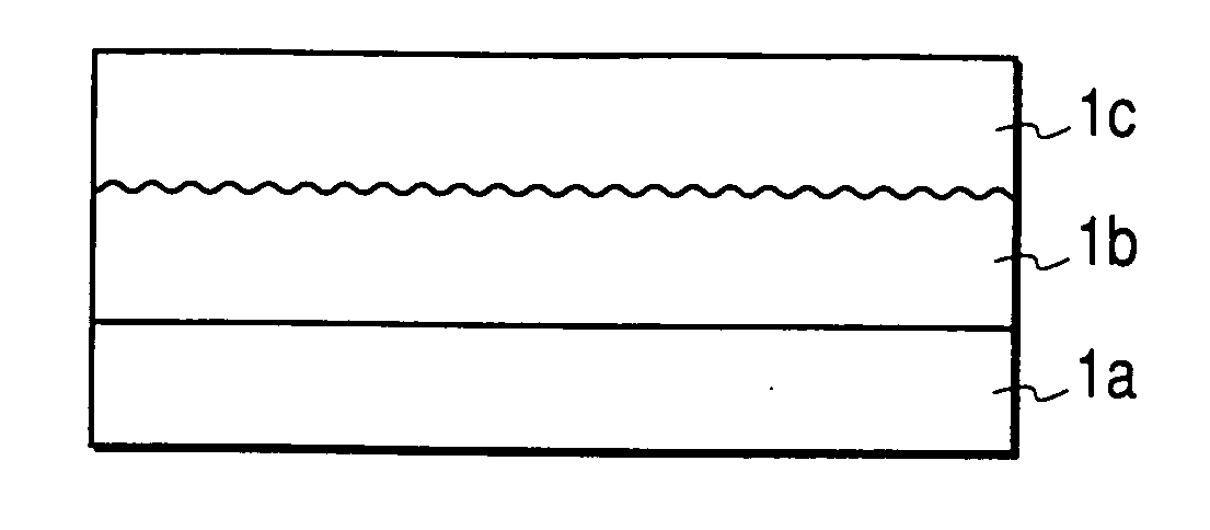
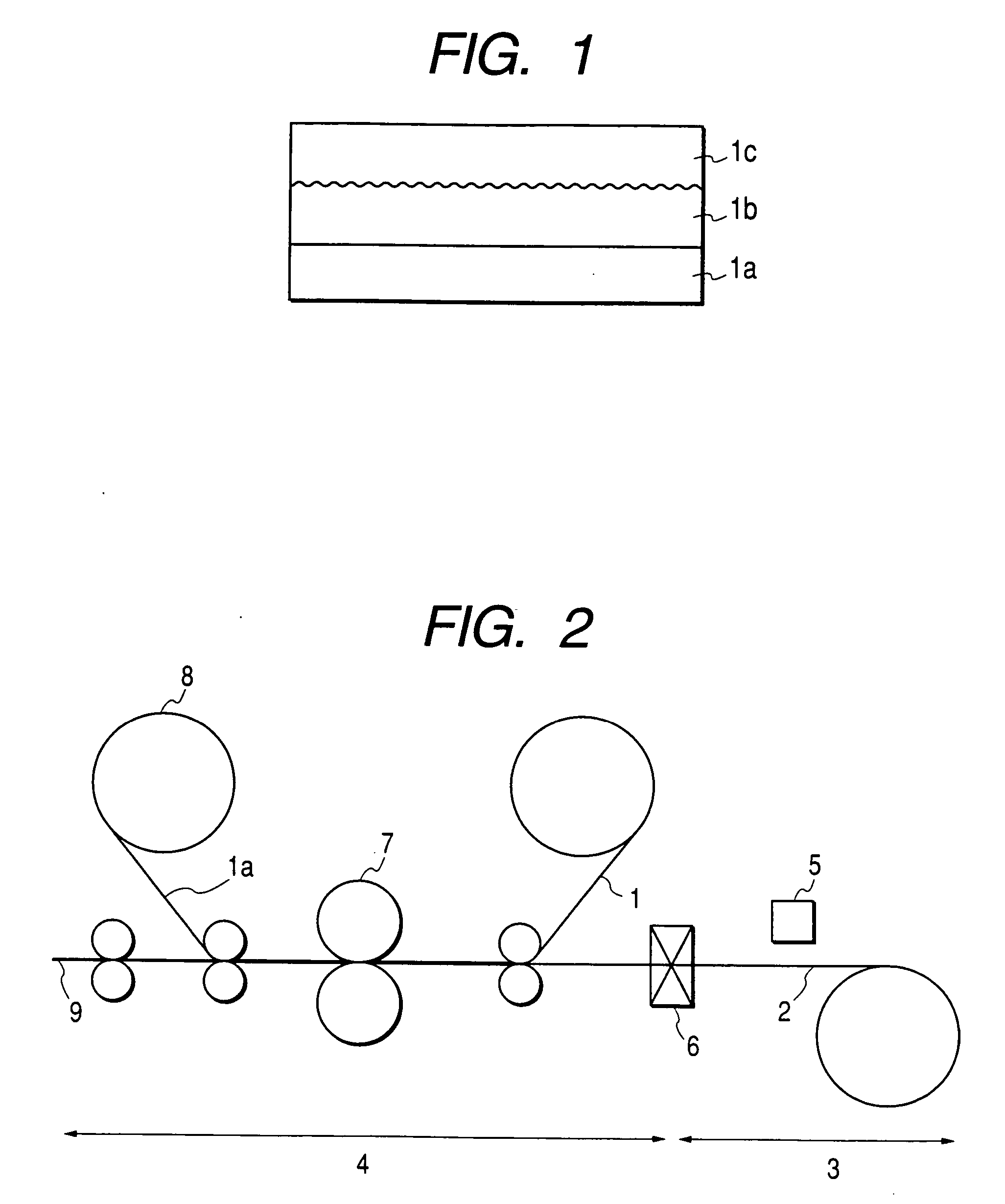
Disclosed herein is a transfer-laminating member including a heat-resistant base material, a release layer provided in part or in whole on the base material and a surface-protecting layer releasably provided on the release layer and formed by applying and drying a coating formulation with a material for forming the surface-protecting layer dissolved in an organic solvent, wherein the release layer contains particles and is formed by curing a mixture which includes a silicone resin, a melamine resin and an alkyd resin.
Description
BACKGROUND OF THE INVENTION [0001] 1. Field of the Invention [0002] The present invention relates to a transfer-laminating member for forming minute irregularities to a transfer-receiving medium. [0003] 2. Related Art [0004] Printed articles by ink-jet, offset printing, gravure printing, electrophotography or the like are known to be improved in fastness properties of images, such as light fastness, water fastness and rub-off resistance, by transfer-laminating a surface-protecting layer on image-formed surfaces (image surfaces) thereof. [0005] As a laminating member, is known a structure that a release layer and a protecting layer have been formed on a base material in that order. In order to improve the visibility of the images, it is known to mat the surface of the surface-protecting layer after transfer. [0006] As methods for matting the surface of the surface-protecting layer, Japanese Patent Application Laid-Open No. 2001-105749 describes methods of causing various kinds of par...
Claims
Login to View More Application Information
Patent Timeline
 IPC IPC(8): B32B7/06B32B27/00B41M7/00B41M5/00B44C1/17C08L61/28C08L67/00C08L67/08C08L83/00C09D161/28C09D167/08C09D183/04
CPCB41M7/0027Y10T428/1476C09D183/04C09D167/08C09D161/28C08L83/00C08L67/08C08L67/00Y10T428/24802B44C1/1733C08L61/28C08L2666/14C08L2666/18Y10T428/31663
InventorIWATA, TETSUKUNIMINE, NOBORU
OwnerCANON KK