
Die seal ring

a technology of sealing rings and dies, applied in the direction of solid-state devices, basic electric elements, electric devices, etc., can solve the problems of dielectric layers, damage, such as chipping, and the risk of mechanical damage in assembly, so as to reduce the risk of mechanical sealing rings failure, reduce the risk of mechanical sealing rings, and increase the distance moisture

Inactive Publication Date: 2011-10-06
QUALCOMM TECH INT
View PDF4 Cites 11 Cited by
  • Summary
  • Abstract
  • Description
  • Claims
  • Application Information

AI Technical Summary

Benefits of technology

[0011]By increasing the impedance through the substrate in the region of the break, the unwanted distribution of signals around the periphery of the die is reduced.
[0016]The seal ring may comprise at least one track and the break may comprise an offset break within a track. This reduces the risk of mechanical seal ring failure and increases the distance moisture or mobile ions would have to diffuse to damage the IC.
[0017]The offset break may be formed using 45° bends. This reduces stresses in the structure and improves reliability.
[0018]The seal ring may comprise at least two tracks and the break may comprise an offset break between tracks. This reduces the risk of mechanical seal ring failure.
[0019]The seal ring may comprise a first and a second track and the at least one break may comprise an offset break within each track and the offset break in the first track may be offset from the offset break in the second track. This further reduces the risk of mechanical seal ring failure.
[0020]The width of the second track may be increased in a region around the offset break within the second track and the width of the first track may be decreased within the same region (i.e. around the offset break within the second track). This provides an electrically effective and compact break in a die seal ring and does not result in an increase in the area of the die which is required for the die seal ring.

Problems solved by technology

The main risk of mechanical damage in assembly arises from cracks in the dielectric layers which may occur when a processed wafer is diced into individual die (e.g. using a wafer saw).
Other damage, such as chipping, may also occur when the wafer is diced.
If moisture ingress is not stopped, the moisture can result in an increase in the dielectric constant of oxides and reduce the reliability of the die through various mechanisms.
The ingress of mobile ions, if allowed, can also affect the reliability and performance of the IC.
The continuous seal ring structure 101 shown in FIG. 1a, however, can be detrimental to the performance of the IC as the seal ring spreads unwanted signals across the die.
Such signals may be picked up from the substrate or by inductive coupling, for example, where the seal ring runs close to a noisy or high power circuit and can cause interference in voltage references, voltage-controlled oscillators, low noise amplifiers and other sensitive analogue circuits.
Increasing the width of the keep-out zone is, however, undesirable as it either results in a larger die or reduces the available area for circuitry.

Method used


Image

  • Die seal ring
  • Die seal ring
  • Die seal ring

Examples


Embodiment Construction

[0040]Embodiments of the present invention are described below by way of example only. These examples represent the best ways of putting the invention into practice that are currently known to the Applicant although they are not the only ways in which this could be achieved. The description sets forth the functions of the example and the sequence of steps for constructing and operating the example. However, the same or equivalent functions and sequences may be accomplished by different examples.

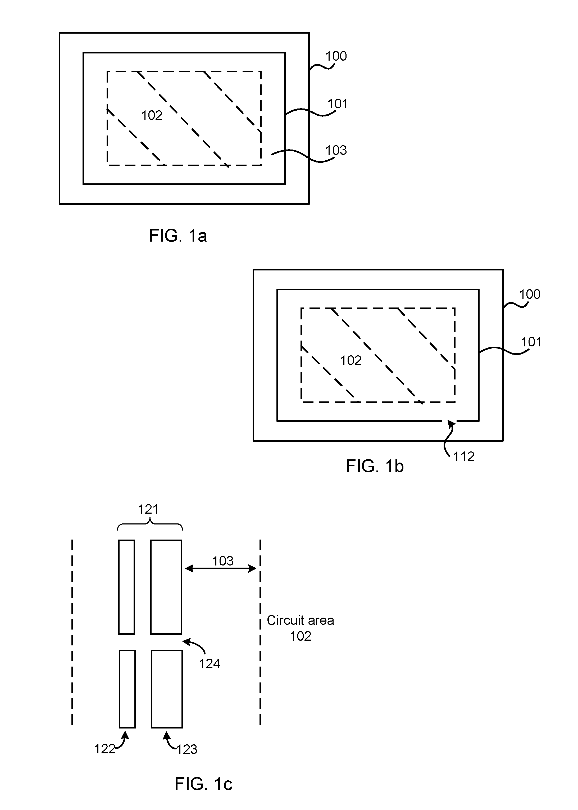
[0041]As described above, in order to reduce coupling of noise through the die seal ring around the perimeter of the die, breaks may be introduced into the die seal ring structure, as shown in FIGS. 1b and 1c. The area where these breaks occur may be referred to as ‘break cells’. Although the term ‘cell’ may refer to a structure which may be a library feature which is used in the layout process for the IC, any reference to a break cell herein refers only to a region of the die seal ring struc...


PUM


Abstract

An improved die seal ring is described which includes at least one break. In the region of the break in the die seal ring, the doping is modified so that the impedance of the electrical path across the break through the substrate is increased. Offsets in the break may also be used and the offset may be within a break in a track and / or between breaks in different tracks, where the die seal ring includes more than one track.

Description

BACKGROUND[0001]Die seal ring structures (also referred to as ‘chip seal rings’ or ‘seal rings’) are commonly used around the periphery of integrated circuits (ICs) in order to protect the circuit components from mechanical damage both during assembly and in operation. The main risk of mechanical damage in assembly arises from cracks in the dielectric layers which may occur when a processed wafer is diced into individual die (e.g. using a wafer saw). These cracks in the dielectric layers may then propagate further into the die if it is thermally cycled (e.g. during assembly or during operation). Other damage, such as chipping, may also occur when the wafer is diced. In operation, the die seal ring protects the chip edge from the diffusion of moisture and mobile ions (also referred to as ‘ionic contamination’) into the die. If moisture ingress is not stopped, the moisture can result in an increase in the dielectric constant of oxides and reduce the reliability of the die through vari...

Claims


Application Information

Patent Timeline
IPC IPC(8): H01L23/58H01L21/22
CPCH01L23/564H01L23/585H01L2924/0002H01L2924/3011H01L2924/00
Inventor HERBERHOLZ, RAINERGODFREY, HOWARD
Owner QUALCOMM TECH INT
Features
  • Generate Ideas
  • Intellectual Property
  • Life Sciences
  • Materials
  • Tech Scout
  • Unparalleled Data Quality
  • Higher Quality Content
  • 60% Fewer Hallucinations
Learn More