Touch screen interface for laser processing

Active Publication Date: 2011-10-06
ELEMENTAL SCI LASERS LLC
View PDF12 Cites 7 Cited by
  • Summary
  • Abstract
  • Description
  • Claims
  • Application Information

AI Technical Summary

Benefits of technology

[0010]The controller can be programmed to offer many different options for responding to user touch screen input. The controller can move the motion stages to cause the image data to move either more or less than the motion input from the screen. This would have the effect of either accelerating specimen motion or making it more sensitive to small motion for fine adjustments. The controller can also interpret some motions relating to Z-axis motion, where moving a finger up and down on the screen, for example, would move the specimen up and down in the field of view, potentially moving the specimen in and out of focus. Other motions can be programmed to move the specimen in 3D, if desired. Alternatively, the controller can be programmed to move the cursor or other screen graphics in response to user touch screen input. For example, in this mode, the user could move the point where the laser beam will impinge upon the specimen by touching the screen and moving the graphic device which indicates the location of the laser beam. The controller then directs the motion stages to move the specim

Problems solved by technology

A problem that computer assisted microscopy systems have in common is that the user needs to select the point on the specimen at which the laser impinges.
Often the specimen is sealed in a sample chamber with limited access.
A problem is that the

Method used


Image

  • Touch screen interface for laser processing
  • Touch screen interface for laser processing
  • Touch screen interface for laser processing

Examples


Example

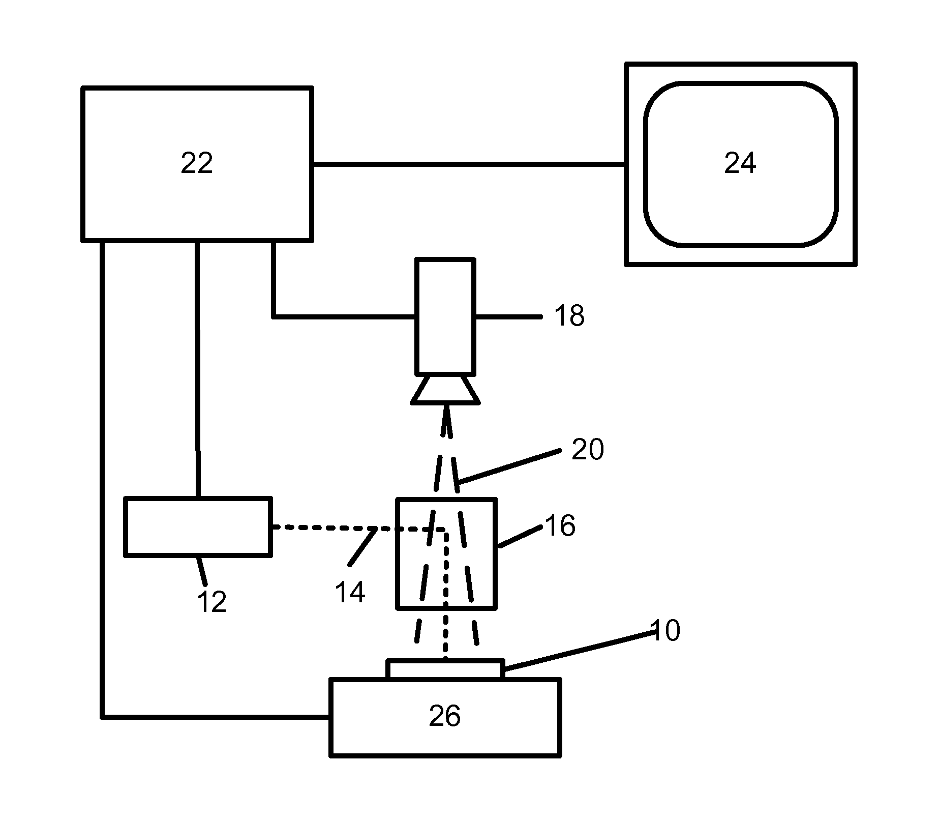
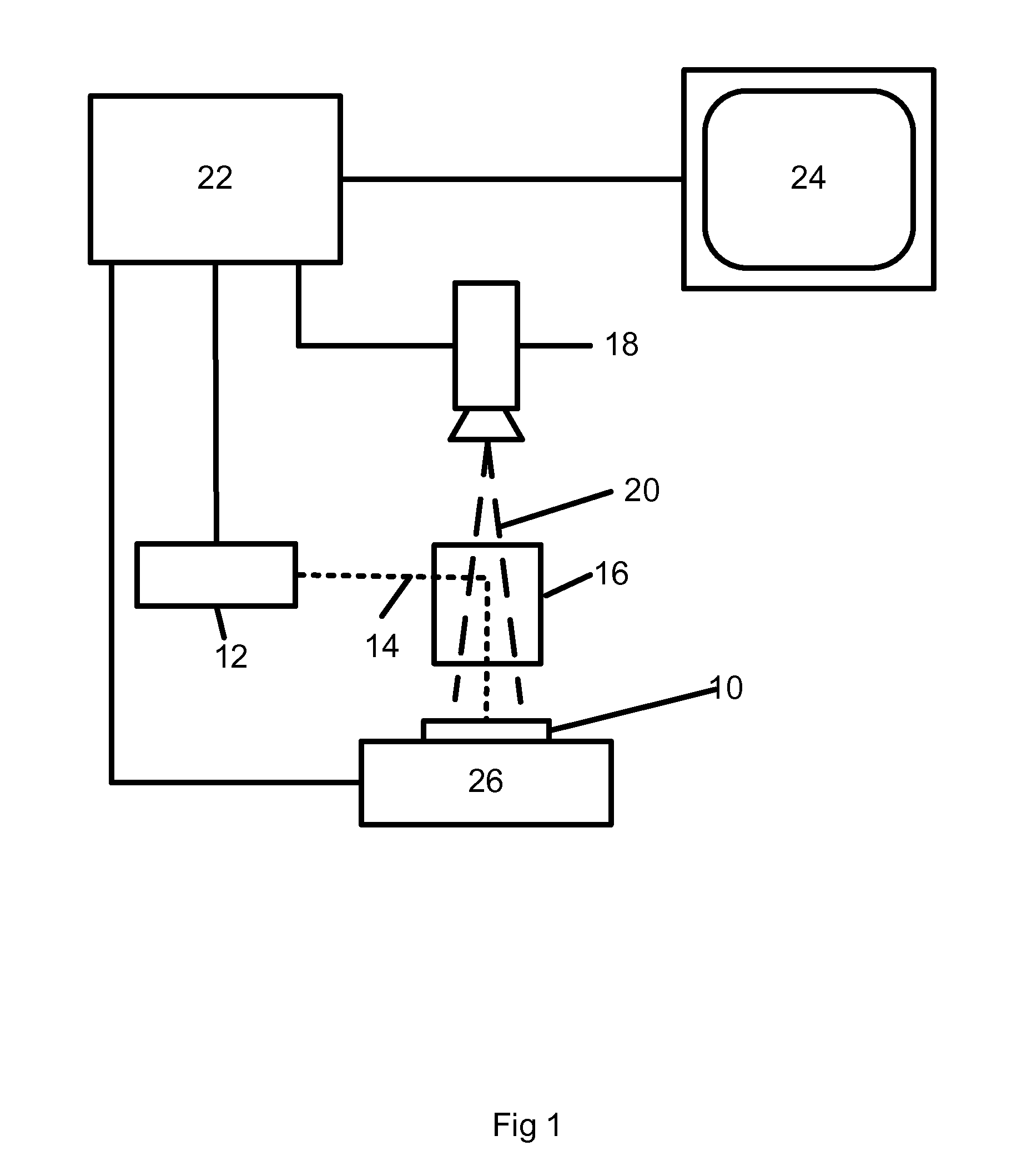
[0017]This invention is a touch screen interface integrated with an optical microscope in a laser processing system. An embodiment of this invention is shown in FIG. 1. This embodiment includes a specimen 10, and a laser 12 having a laser beam 14. The laser beam 14 is directed to the specimen 10 by an optical microscope 16. This optical microscope 16 is an exemplary optical device which combines the optical axes of the laser 10 and the camera field of view 20 to permit the camera 18 to image the portion of specimen 10 that falls within the field of view 20. Other optical devices can also be used to combine the laser beam 14 and camera field of view 20, for example a half-silvered mirror (not shown). In addition, the system can be constructed so that the camera field of view 20 and the laser beam 14 are not on the same optical axis and therefore require separate optical devices (not shown) to direct the laser beam 14 and camera field of view 20. In this case the controller 22 calcula...


PUM


Abstract

A touch screen user interface for an optical device wherein the touch screen user interface is connected to a controller which controls motion stages permitting the motion stages to re-position, re-size, re-orient or focus the field of view of the optical device in response to commands input from the touch screen user interface.

Description

TECHNICAL FIELD[0001]This invention is a touch screen user interface for imaging devices. In particular it is a touch screen interface for microscopy systems, wherein the microscope has motion stages for holding the specimen to be examined and where the touch screen user interface is connected to a controller which receives commands from the touch screen user interface and converts them into commands which drive the motion stages. In more particular it is a touch screen user interface for optical microscopy wherein the user can enter commands to the system via touch screen user interface and have the motion stages respond to those commands as if the user had moved the specimen directly rather than touching an image of the specimen on a touch screen.BACKGROUND OF THE INVENTION[0002]The field of optical microscopy is broad, encompassing many types of optical and other devices which rely upon magnification to image or examine or extract information regarding specimens that are smaller ...

Claims


Application Information

Patent Timeline
IPC IPC(8): H04N7/18B01D59/44
CPCB23K26/032G02B21/26B23K26/0853
Inventor SUMMERFIELD, LEIFCLEM, BILLWILKINS, JAYWERNIKOWSKI, TOMBERNASEK, JAY
Owner ELEMENTAL SCI LASERS LLC
Why Eureka
Try Eureka