Switching power unit

a power unit and power technology, applied in the direction of electric variable regulation, process and machine control, instruments, etc., can solve the problems of excessive increase of pfc voltage of inability to further narrow the on-duty of the switching element, and difficulty in controlling the power-factor improvement unit that shares the switching elements. , to achieve the effect of simplifying the structure, reducing the number of parts, and good cost performan

Active Publication Date: 2011-10-06
MINEBEAMITSUMI INC
View PDF1 Cites 31 Cited by
  • Summary
  • Abstract
  • Description
  • Claims
  • Application Information

AI Technical Summary

Benefits of technology

[0042]Further, the present invention would be possible to reduce a number of parts, being able to achieve a good cost performance and a simplified structure since there is no need to provide a full-wave rectifier and the first and the second switching elements Q1 and Q2 are sharable, even though a full-bridge-method is used. Still further, by reducing switching loss and eliminating the multi-stages of its circuit structure, efficiency of the switching power unit of the present invention is more improved compared with a conventional method.

Problems solved by technology

However, since the above-described half-bridge circuit is designed as that the on-duty of the switching elements is approximately 50%, it would be difficult to control the power-factor improvement unit that shares the switching elements.
For example, even when loads are relatively small, the on-duty of the switching element cannot be further narrowed.
Accordingly, the PFC voltages of the power-factor improvement unit excessively increase, whereby there is a risk that the switching elements or the capacitor may be damaged.
However, considering a switching power circuit disclosed in FIG. 9, since the on-duty of switching elements is fixed to approximately 50%, when the instantaneous value of the AC input voltages and the value of PFC voltage come closer, it would become difficult to appropriately perform power-factor improvement operations.
The general inverter outputs positive polarities and negative polarities in an alternative manner; however, the above operations are not in conformity therewith.
The operations do not thus necessarily fit to optional loads.
Accordingly, it would be difficult to control the power-factor improvement unit that shares the switching elements.

Method used


Image

  • Switching power unit
  • Switching power unit
  • Switching power unit

Examples


first embodiment

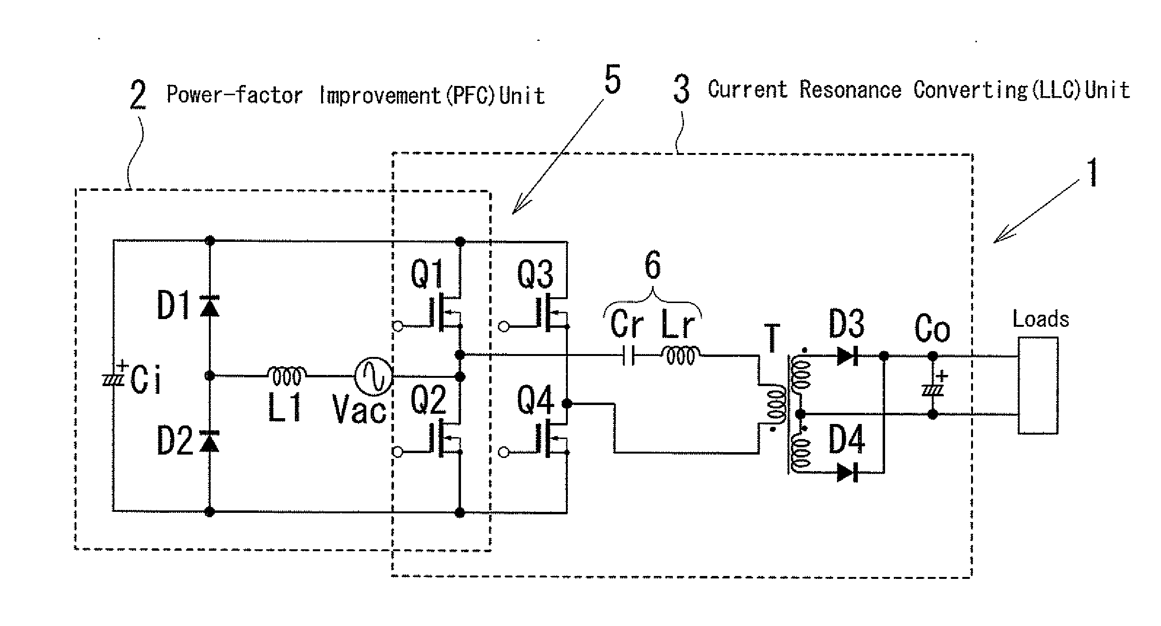
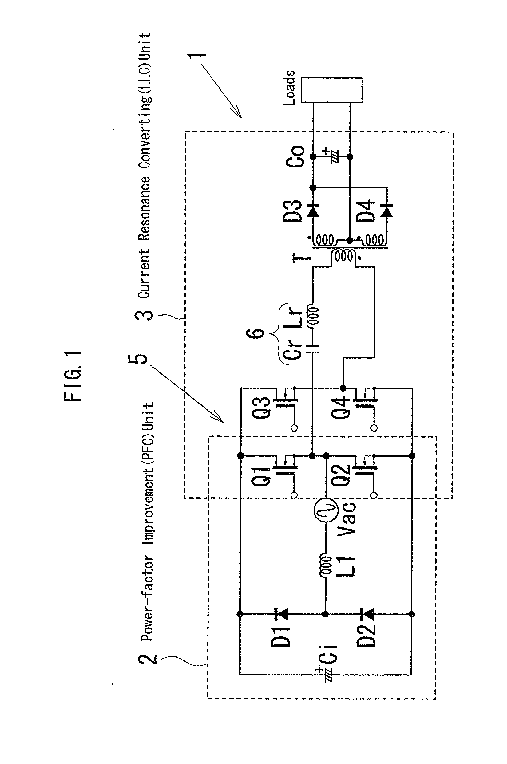
[0053]Preferred embodiments of the present invention will be described with reference to the accompanying drawings. FIG. 1 is a block diagram that shows an AC / DC converter circuit 1 that is the basic architecture of a switching power unit according to the present invention. The AC / DC converter circuit 1 as the main portion of the switching power unit shown in FIG. 1 is composed of a power-factor improvement (PFC) unit 2 and a current resonance converter (LLC) unit 3.

[0054]In the power-factor improvement unit 2, the series circuit of first and second diodes D1 and D2 and the series circuit of first and second switching elements Q1 and Q2 are connected in parallel. A booster inductor L1 and an AC source Vac are connected in series at the intermediate point of both series circuits. A first smoothing capacitor Ci is connected at the both ends of the series circuit of the first and the second diodes D1 and D2 in parallel with first and second switching elements Q1 and Q2.

[0055]The curren...

fourth modified embodiment

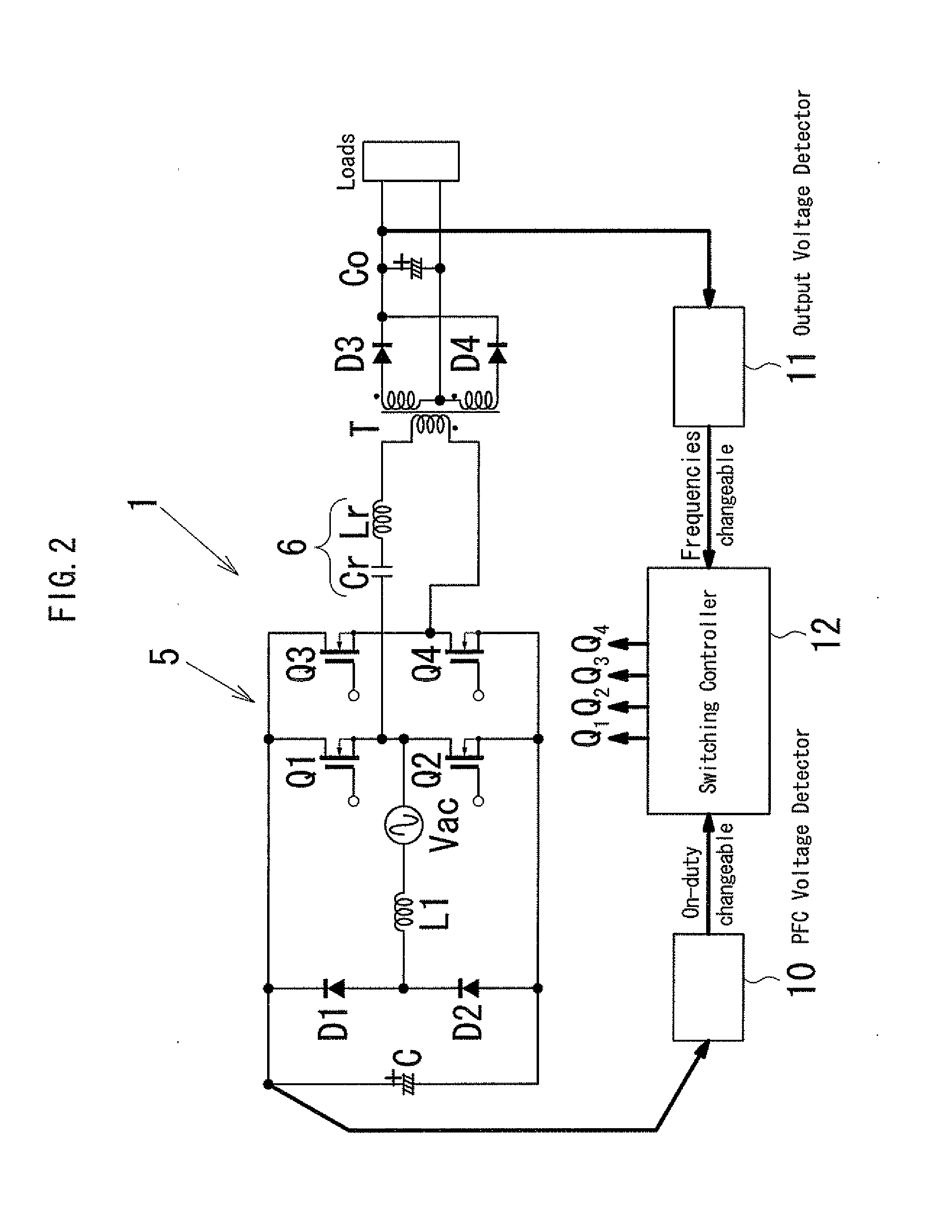
[0078]FIG. 7 shows the present invention where a switching controller 12 is arranged on the secondary circuit side. Here, output signals from a PFC voltage detector 10 on the primary side are transmitted to the switching controller 12 on the secondary side through an insulation means (a second insulation means). On the other hand, switching controlling signals output from the switching controller 12 based on output signals from an output voltage detector 11 on the secondary side and output signals from the second insulation means are transmitted to the switching elements Q1 to Q4 on the primary side through a third insulation means. Further, detected results obtained at a polar detector 13 on the primary side are transmitted to the switching controller 12 on the secondary side through a fourth insulation means.

[0079]In this circuit of the fourth modified example, as the same with the third modified example, each insulation means (the second to the fourth insulation means) is formed ...


PUM


Abstract

There is provided switching power unit comprising: a PFC voltage detector that detects PFC voltages of the power-factor improvement unit; an output voltage detector that is provided in a current resonance converter unit; a switching controller into which output signals from the PFC voltage detector and output signals from the output voltage detector are input, wherein the switching controller in a full-bridge circuit of first to fourth switching elements, based on output signals from the PFC voltage detector and the output voltage detector, controls the PFC voltages by changing on-duty of the first and second switching elements, and also controls the output voltages by changing switching frequencies of the full-bridge circuit.

Description

BACKGROUND OF THE INVENTION[0001]1. Field of the Invention[0002]The present invention relates to an AC / DC converter provided with a power-factor improvement (PFC) unit and a current resonance (LLC) converter unit, more particularly to a switching power unit that can achieve highly effective performances through a power-factor improvement operation and an output voltage control by changing the on-duty and the switching frequency of a full-bridge type switching element.[0003]2. Description of the Related Art[0004]For digital apparatuses or home-use amusement equipments such as laptop computers, liquid crystal televisions, plasma televisions, game machines, a switching power unit that is provided with an AC / DC converter in which to improve a power-factor has been used. In general, the switching power unit is composed of a full-wave rectifier bridge, a booster type power-factor improvement (PFC) unit and a DC / DC converter portion.[0005]For the DC / DC converter portion, a flyback type con...

Claims


Application Information

Patent Timeline
Patent Type & Authority Applications(United States)
IPC IPC(8): H02M3/335
CPCH02M1/4258Y02B70/1441Y02B70/126H02M2007/4815H02M7/4815Y02B70/10
Inventor MINAMI, EIJIMASUDA, SHIGEMI
Owner MINEBEAMITSUMI INC
Why Eureka
Try Eureka