Rigid window applicator and method

a window applicator and window technology, applied in the field ofrigid window applicators and methods, can solve the problems of misfeeding carton blanks, more complex and costly male and female dies, and limited speed, and achieve the effect of improving operation

Inactive Publication Date: 2011-10-06
TAMARACK PRODS
View PDF48 Cites 8 Cited by
  • Summary
  • Abstract
  • Description
  • Claims
  • Application Information

AI Technical Summary

Benefits of technology

[0011]The instant invention enhances the operation of a combination of prior art machinery: a carton folder gluer and a Tamarack Vista® window applicator equipped with an optional die cut station. The present invention provides a new way of webbing the window material that utilizes a die cut station's anvil cylinder as a feeding cylinder. This new webbing approach also allows the die cut to operate at an essentially constant rate of rotation while accommodating the Vista® applicator's stop-and go operation.

Problems solved by technology

This has practical limitations on speed as it uses a reciprocating punching station with male and female dies.
Male and female dies are more complex and costly than a rotary die cylinder and rotary die cylinders are easy to set up and operate.
In systems where the adhesive pattern is applied to the carton blank, when a window misfeeds, i.e., is not placed in the proper location on the carton, or is missing altogether, the adhesive transfers onto various conveying components, e.g., transport belts, rollers and folding swords, fouling them with adhesive that can cause misfeeding of the carton blanks and the need to clean conveying belts and rollers to restore proper function.
Until the instant invention, however, the Vista® window applicator has not been adapted to process rigid window materials.

Method used


Image

  • Rigid window applicator and method
  • Rigid window applicator and method
  • Rigid window applicator and method

Examples


Embodiment Construction

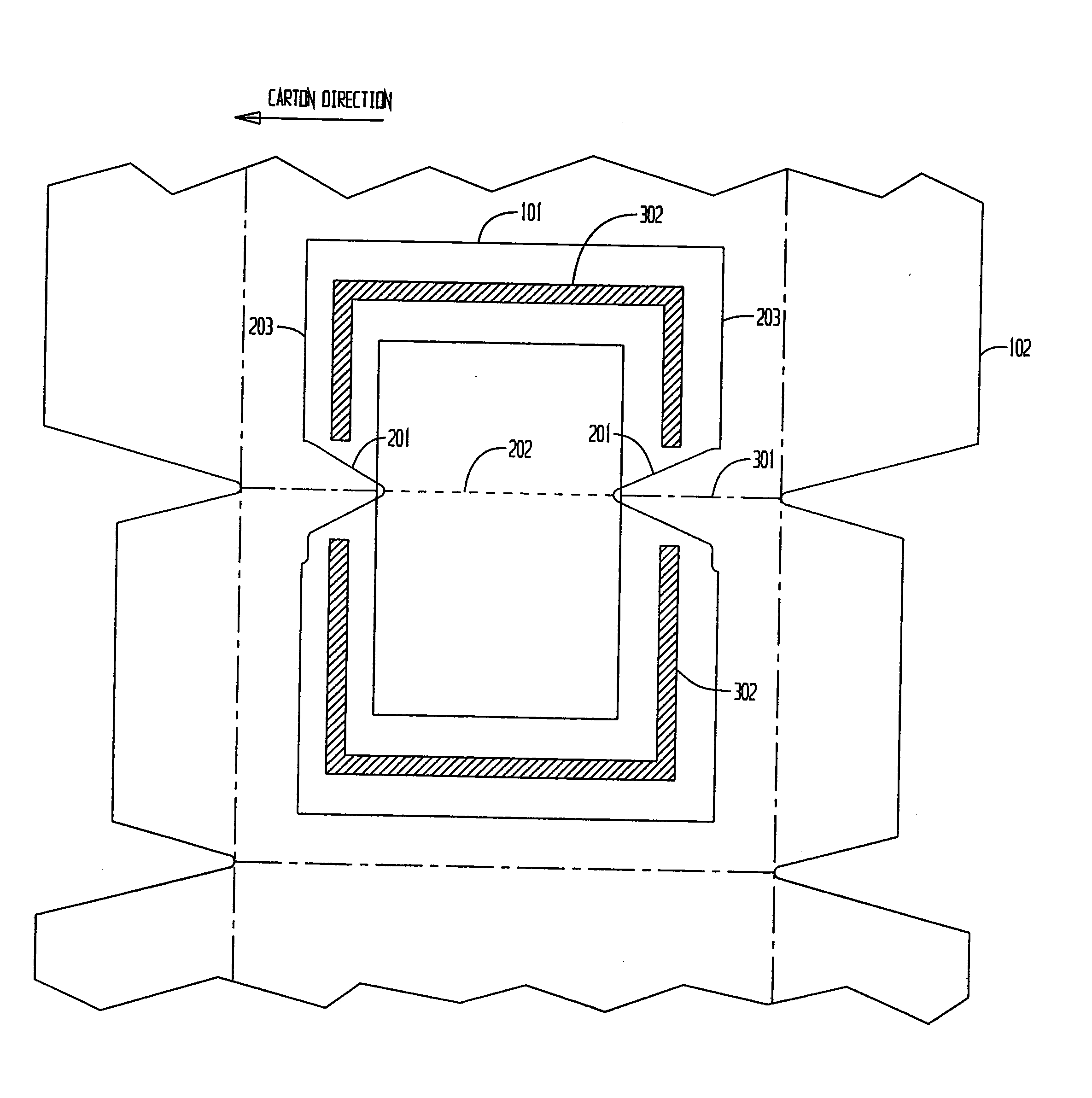
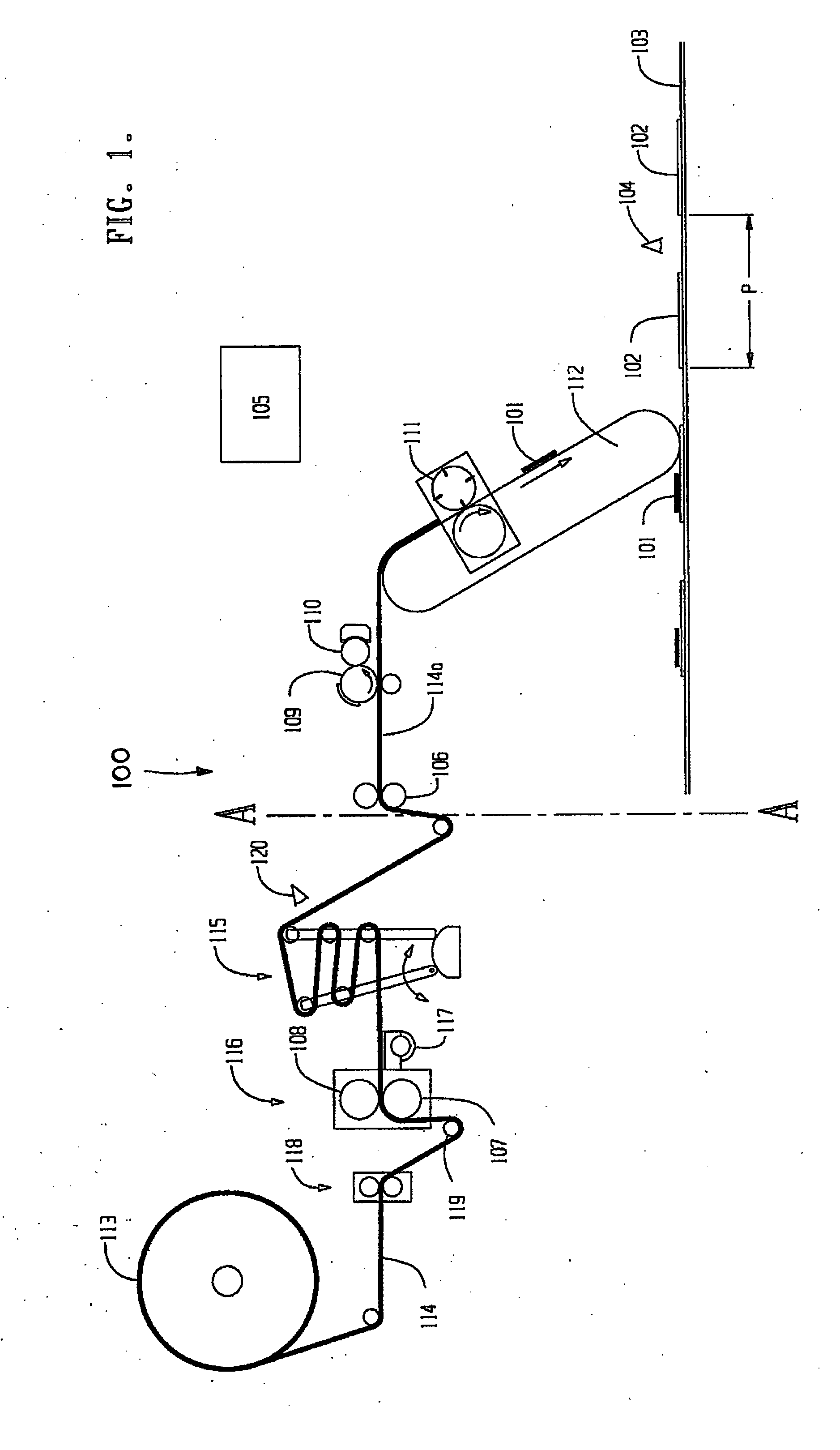
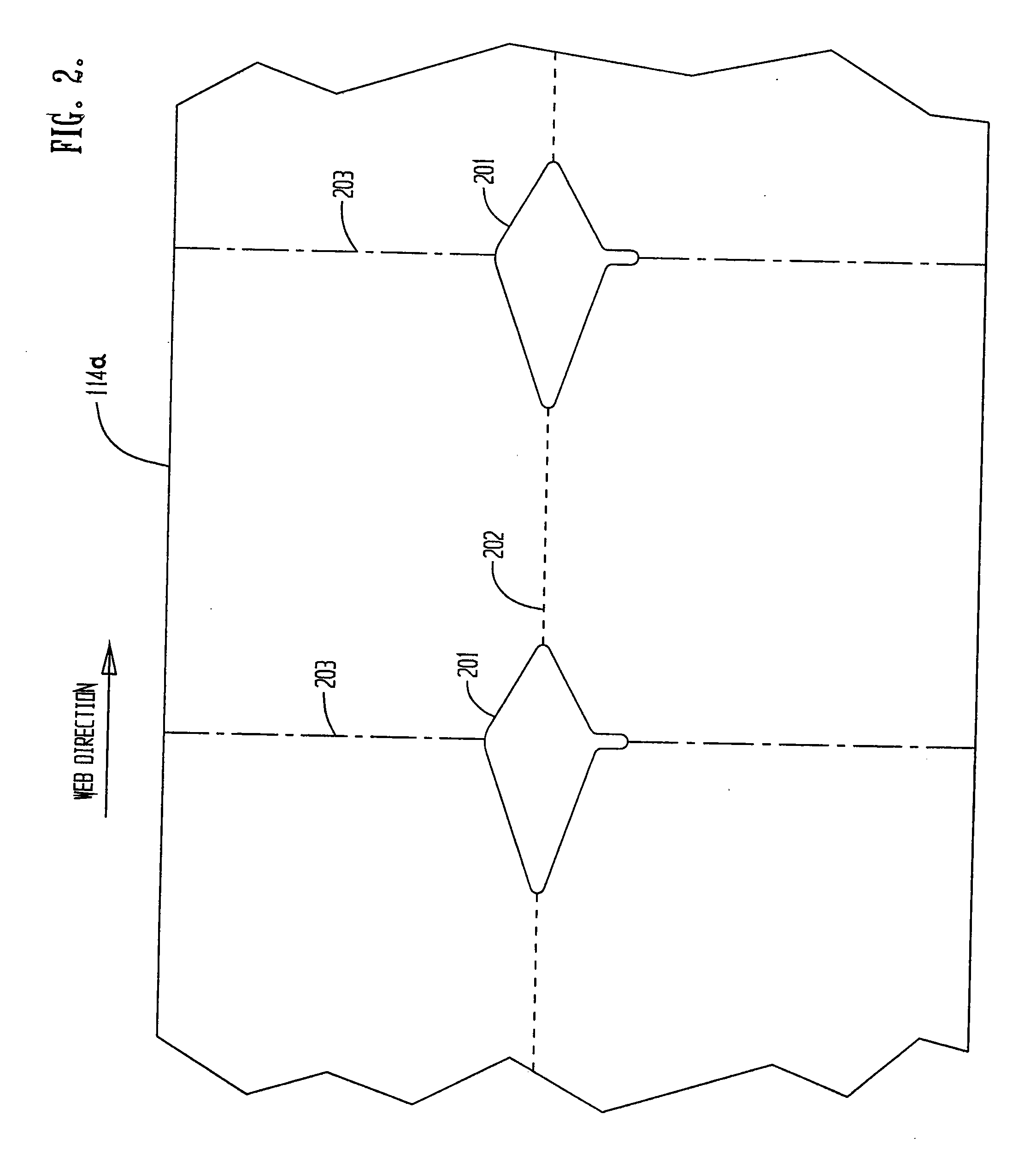
[0032]FIG. 1 is a schematic side view of a prior art Tamarack Vista® window applicator 100 installed on a carton folding / gluing machine which has been modified to provide rigid windows by adding a die cutting station in accordance with the present invention. Window applicator 100 is a device that supplies window patches 101 onto folding carton blanks 102. The carton blanks 102 are conveyed by transport, or carrier belt 103 of a carton folder gluer such as provided by Bobst of Lausanne, Switzerland. The lead edge or other feature on a folding carton blank 102 is sensed by a scanner 104 such as provided by Keyence of Osaka, Japan. The scanner signal is transmitted to a servo control system 105 which processes the signal and communicates with servo axes for the feeding roller 106, the die cut cylinders 107, 108, the gluing cylinders 109, 110, and the cutting cylinder 111. The control system 105, such as EcoDrive or IndraDrive supplied by Bosch Rexroth of Erbach, Germany and programmed ...


PUM


Abstract

Apparatus and method for affixing rigid transparent windows to folding cartons draws rigid window web material from a roll and scores and notches the window material in a continuous manner. Notch waste is removed and collected for disposal by the combination of vacuum and an air jet applied at the point of severance. The transparent window material is then provided to an accumulator and then to a stop-and-go adhesive application and material cutting stage, where adhesive is applied to the material which is cut into individual rigid window patches, with the accumulator serving as a buffer between the high speed continuous scoring and notching stage and the stop-and-go adhesive application and cutting stage. Adhesive-bearing individual window patches are applied to moving folding cartons with registration between the notches and cut lines as well as between the cut window blanks and carton blanks provided by a control system.

Description

FIELD OF THE INVENTION[0001]This invention relates generally to the application of a window film over a die cut opening in a folding carton, and is particularly directed to the formation of rigid windows from rolls of rigid window materials and the application of the thus formed rigid windows to folding cartons in a single, high speed operation.BACKGROUND OF THE INVENTION[0002]Window film is often applied over a die cut opening in a folding carton to provide a way to view the contents inside the carton. The window may be within the perimeter of one or more panels of the carton.[0003]Windows in more than one panel of a carton are often referred to as panoramic windows, particularly if the window continuously extends from one panel, across the score or crease line at a corner of the carton, and into an adjacent panel.[0004]In larger cartons, or in cartons containing more expensive or attractive contents, a substantially thicker window, approximately 0.007″ or thicker is used, as oppos...

Claims


Application Information

Patent Timeline
Patent Type & Authority Applications(United States)
IPC IPC(8): B31B1/82
CPCB31B1/00B31B2203/082B31B2201/9076B31B50/00B31B50/82B31B2100/0022
Inventor MACHAMER, DAVID E.SLAGER, THOMAS S.
Owner TAMARACK PRODS
Why Eureka
Try Eureka