Tire condition monitoring method and tire condition monitoring system

Active Publication Date: 2011-10-06
YOKOHAMA RUBBER CO LTD
View PDF2 Cites 17 Cited by
  • Summary
  • Abstract
  • Description
  • Claims
  • Application Information

AI Technical Summary

Benefits of technology

[0008]The present technology provides a tire condition monitoring method and a monitoring system having a simple configuration and that can process data with a high degree of reliability. A tire condition monitoring method of the technology provides a tire condition monitoring method for measuring a physical property value in a tire by a sensor of a sensor module mounted in the tire, transmitting data of the physical property value from the sensor module at a desired time interval, receiving the data from the sensor module by a receiver, and monitoring the physical property value based on the data received by the receiver. The method includes a step of processing send data by determining at the sensor module if a measured value from the sensor satisfies a preset condition and, if determined that the measured value does not satisfy the preset condition, at least one flag is set in a data packet transmitted from the sensor module. The method also includes a step of processing received data by determining at the receiver whether the flag is set in the received data if determined that the received data does not satisfy a preset condition. If determined that the flag is included in the received data the received data is used, and if determined that the flag is not included, the received data is discarded.
[0010]According to the technology, when a measured value from a sensor does not satisfy a preset condition, at least one flag is set in a data packet to be transmitted from a sensor module. When the measured value does not satisfy the preset condition, at the receiver, the state of the flag of the received data is checked. The received data is used only when the flag is present. When the flag is absent, the received data is discarded. Therefore, it is possible to increase the reliability of the data without using error-correcting codes.
[0011]Additionally, when an amount of change of a measured value with respect to a previous value exceeds a preset threshold value from the sensor, at least one flag is set in the data packet to be transmitted from the sensor module. The received data is compared to the previous value at the receiver, and if the amount of change of the received data with respect to the previous value exceeds the threshold value, the state of the flag of the received data is checked. The received data is used only when the flag is present. When the flag is absent, the received data is discarded. Therefore, it is possible to increase the reliability of the data without using error-correcting codes.
[0012]Moreover, when a measured value from the sensor exceeds a preset threshold value, at least one flag is set in the data packet to be transmitted from the sensor module. If the received data exceeds the threshold value at the receiver, the state of the flag of the received data is checked. The received data is used only when the flag is present. When the flag is absent, the received data is discarded. Therefore, it is possible to increase the reliability of the data without using error-correcting codes.
[0016]Additionally, when the sensor acquires data that satisfies an additional requirement of the flag, the flag is set, and, preferably, at the same time, data transmission from the sensor module is performed via a second transmission interval that is shorter than a normal first transmission interval. Furthermore, it is more preferable that the second transmission interval be ½ of the first transmission interval or shorter. Thus, when anomalous data is detected, data transmission is performed via a shorter transmission interval, and therefore the reliability of the data can be further increased.
[0017]Additionally, when an abnormal value in which a flag was not set at the receiver is acquired three times or more, it is preferable for the error to be determined to be due to the receiver. Thereby, the possibility of data being continuously discarded due to an error of the receiver can be eliminated.

Problems solved by technology

However, in rare cases, anomalous data that differs greatly from genuine data passes through the error detecting test and is accepted as genuine data.
The probability of such misdetections occurring is high, especially in tire condition monitoring systems for use in trucks that have many sensor modules.
Additionally, it is possible to increase the reliability of the data by using error-correcting codes such as BCH (Bose Hocquenghem Ray-Chaudhuri codes) or Hamming codes, but in this case, the data becomes redundant and the program becomes complicated.
A complicated program is a factor that leads to an increase in equipment costs of tire condition monitoring systems.

Method used


Image

  • Tire condition monitoring method and tire condition monitoring system
  • Tire condition monitoring method and tire condition monitoring system
  • Tire condition monitoring method and tire condition monitoring system

Examples


first embodiment

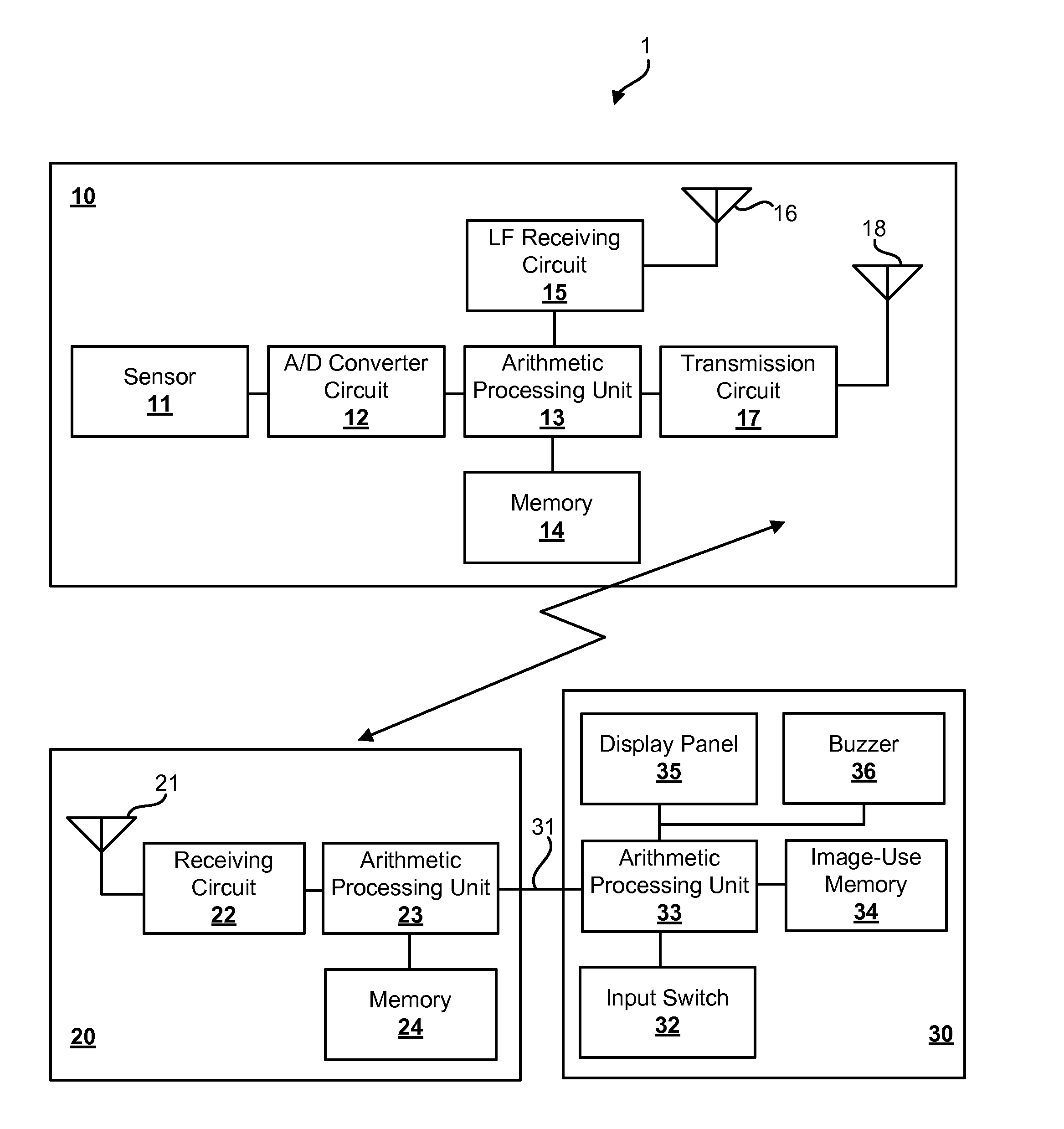
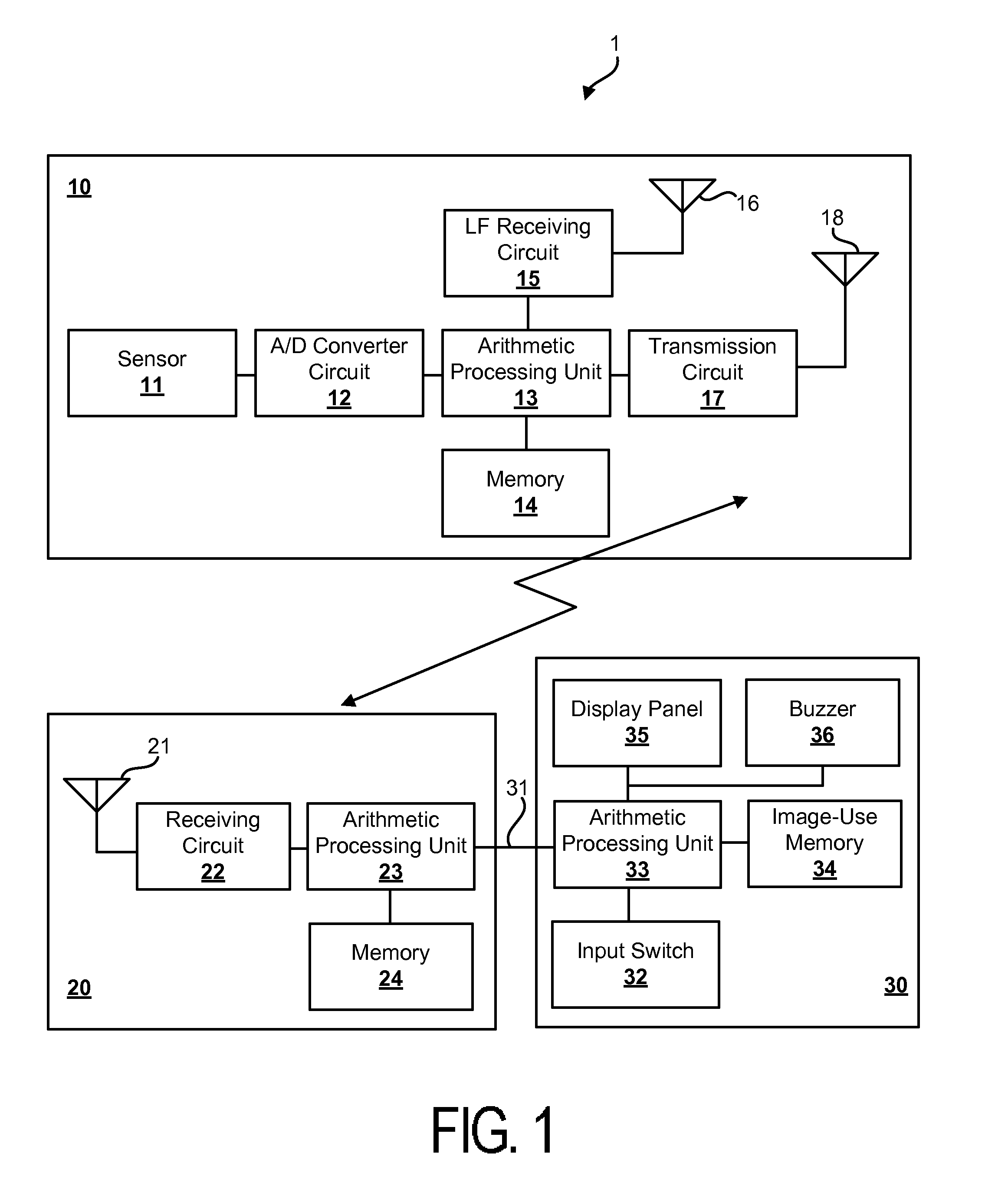
[0023]Detailed descriptions will be given below of a configuration of the technology with reference to the accompanying drawings. FIG. 1 is a component diagram illustrating a tire condition monitoring system of the technology. The configuration of the tire condition monitoring system can be applied to both the first technology and the second technology by changing the functions of the first arithmetic processing unit and the second arithmetic processing unit.

[0024]As illustrated in FIG. 1, a tire condition monitoring system 1 includes a sensor module 10, a receiver 20, and a monitoring device 30. The sensor module 10 is mounted in a tire (on a tire inside surface or on a rim peripheral surface), the receiver 20 is mounted on a vehicle body part of a vehicle, and the monitoring device 30 is mounted on a driver's seat of the vehicle.

[0025]The sensor module 10 includes a sensor 11 that detects a physical property value in the tire, an A / D converter circuit 12 that is connected to the s...

second embodiment

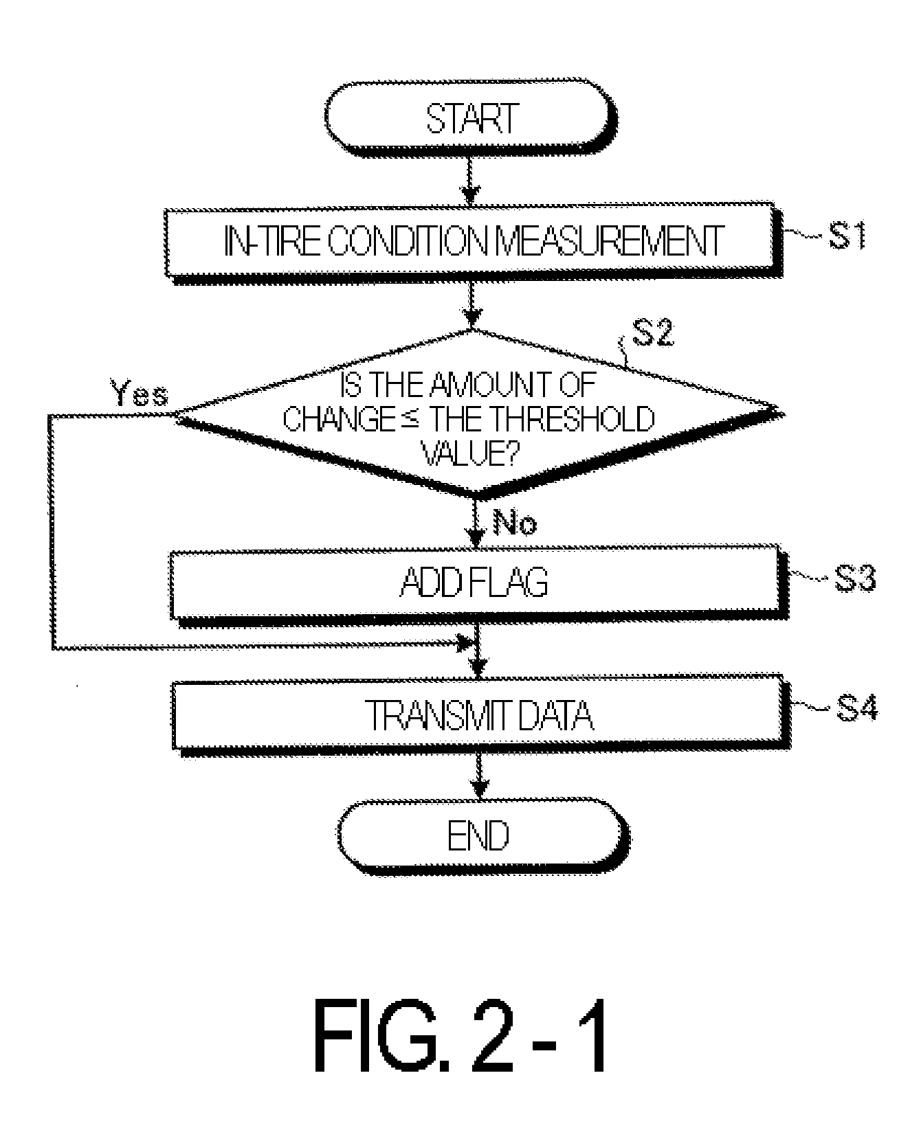
[0043]Next, another method for monitoring a temperature in a tire using the tire condition monitoring system 1 described above will be described using FIGS. 3-1 and 3-2. Here, FIGS. 3-1 and 3-2 are flowcharts illustrating the tire condition monitoring method of the technology. More specifically, FIG. 3-1 is a flowchart illustrating processing performed in the sensor module and FIG. 3-2 is a flowchart illustrating processing performed in the receiver and the monitoring device.

[0044]First, as illustrated in FIG. 3-1, the sensor module 10 measures the temperature as the physical property value in the tire (step S11) via the sensor 11. The sensor module 10 inputs the temperature data detected by the sensor 11 into the arithmetic processing unit 13 after converting the data from analog data to digital data via the A / D converter circuit 12. The arithmetic processing unit 13 compares the measured value from the sensor 11 with a preset threshold value and determines if the measured value is...


PUM


Abstract

A tire condition monitoring method and a monitoring system having a simple configuration and that can process data with a high degree of reliability. The method or system determines at a sensor module whether a measured value from a sensor satisfies a preset condition. If determined that the measured value does not satisfy the preset condition, at least one flag is set in the data packet to be transmitted from the sensor module. If, at the receiver, it is determined that the measured value of the received data does not to satisfy a preset condition, whether a flag is included in the received data is determined. If it is determined that the received data includes a flag, the received data is used, and if it is determined that a flag is not included, the received data is discarded.

Description

BACKGROUND[0001]1. Technical Field[0002]The technology relates to a tire condition monitoring method and a tire condition monitoring system for monitoring tire conditions.[0003]2. Related Art[0004]Systems exist for monitoring tire conditions. For example, tire condition monitoring systems exist that include a sensor module having a sensor that is disposed in a tire and that detects a physical property value of the tire, and a transmitter that outputs the physical property value acquired by the sensor; a receiver that receives information output from the transmitter; and a monitoring device that monitors a tire condition based on the information received from the receiver. In such tire condition monitoring systems, the acquired physical property value data is sent from the transmitter to the receiver.[0005]Additionally, in the field of communications, when communicating data, it is common practice to insert a cyclic redundancy check (CRC) in a data packet as a technology for detectin...

Claims


Application Information

Patent Timeline
IPC IPC(8): B60C23/02
CPCB60C23/044B60C23/0455B60C23/0462B60C23/0481G01K1/024H04Q2209/826G01K13/08G01M17/02H04Q9/00H04Q2209/40H04Q2209/823G01K3/005B60C23/04B60C23/20G01L17/00G01K1/02
Inventor ARAKI, YASUHIKOKANENARI, DAISUKE
Owner YOKOHAMA RUBBER CO LTD
Why Eureka
Try Eureka