Source localization using multiple units of a tight-pitched detector array

a detector array and source technology, applied in the field of systems and methods for detecting radiation sources, can solve the problems of inability to take advantage of choke points to locate radiation sources, inability to estimate the position of radiation sources (x,y), and inability to take advantage of choke points. to achieve the effect of increasing the signal-to-noise ratio

Inactive Publication Date: 2011-10-06
UCHICAGO ARGONNE LLC
View PDF3 Cites 17 Cited by
  • Summary
  • Abstract
  • Description
  • Claims
  • Application Information

AI Technical Summary

Benefits of technology

[0009]Various embodiments of the present systems and methods incorporate radiation detection and processing, of statistical and deterministic phenomena, to generate a statistically qualified best estimate for source direction employing a single directional detector. In other embodiments, multiple detector units operating in an integrated fashion yield information describing source location and location uncertainty. While conventional detectors that use a single detector element to seek out a source lack directional capability, the present directional detectors are configured to pr

Problems solved by technology

In the confined-venue problem pedestrian traffic enters through a limited number of entrances or what are effectively choke points.
On the other hand, in the wide-area problem access to the venue is less controlled both in time and space.
For example, a ship boarding party inspecting a vessel and its cargo whose disposition is not well characterized is unable to take advantage of choke points to locate a radiation source.
Further examples of wide-area problems include large open-air events, such as an inauguration, having many pedestrian approaches, some of which are large spaces with no choke point.
Significantly, existing radiation detection systems are not capable of estimating an (x,y) position for a radiation source.
Although existing directional detectors can estimate a direction, they cannot provide a probability of locating a source as a function of direction.
Current directional-detector technology is further limited as such systems generally operate as a standalone unit without the capability for sharing data among several units to improve the accuracy of the source position estimate.
Existing directional detection methods also do not provide an

Method used


Image

  • Source localization using multiple units of a tight-pitched detector array
  • Source localization using multiple units of a tight-pitched detector array
  • Source localization using multiple units of a tight-pitched detector array

Examples


Embodiment Construction

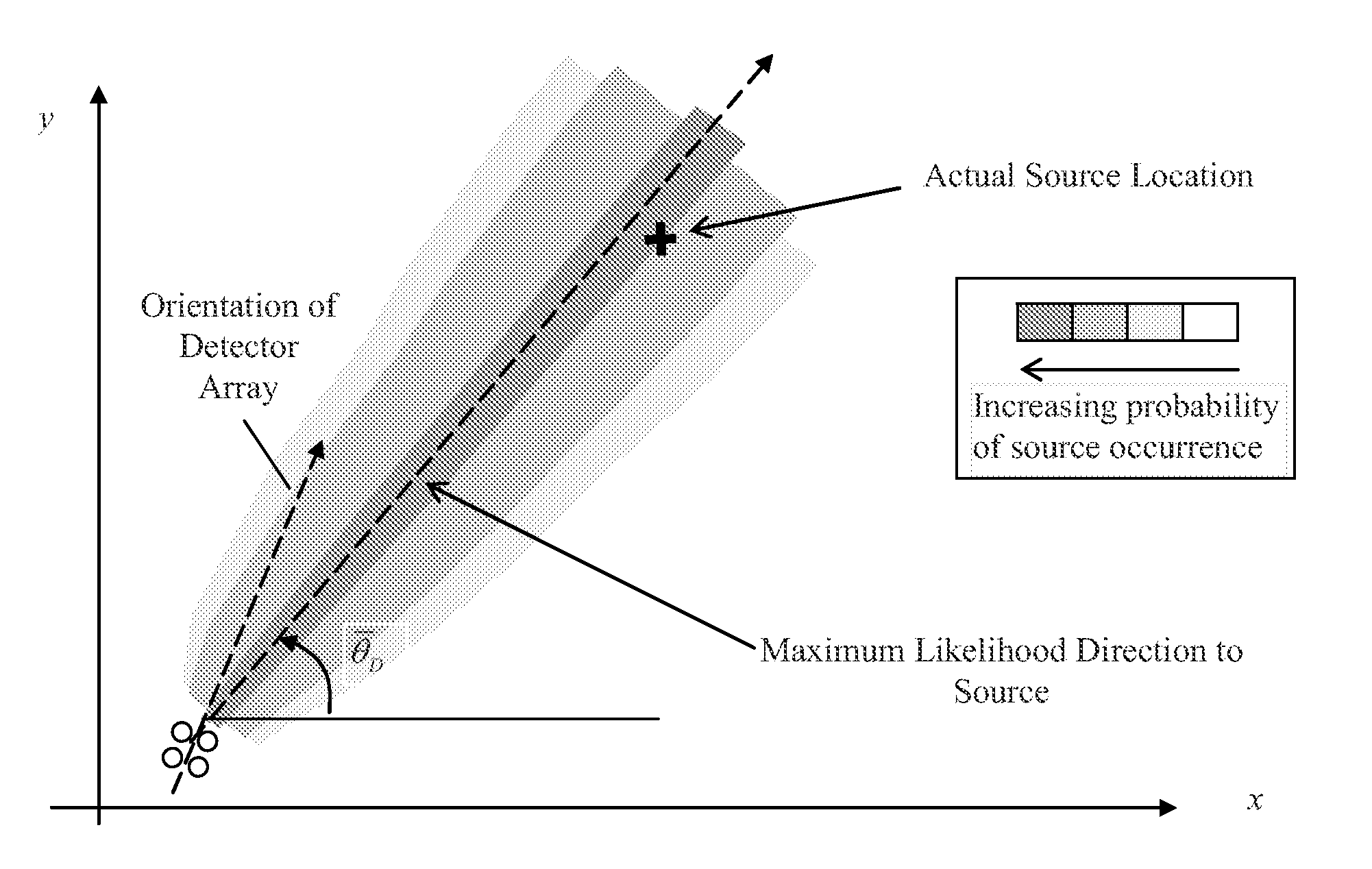
[0030]According to an embodiment, a directional radiation detector obtains source directionality by either placing an absorbing medium between detector elements, which are arranged in an array, or by positioning the individual detector elements such that the view of the source by each detector is partially occluded. The degree of occlusion is a function of the orientation of the array with respect to the source. Processing of count rate data associated with the detector unit relates relative count rates in individual detector elements with the direction of the incoming radiation. Processing of count rate data may be accomplished in near real-time to achieve efficient detection and tracking of a radiation source within an environment. The relationship between count rate and array orientation needed to infer source direction may be established a priori, for example, in the laboratory or through simulations.

[0031]Various embodiments of the present systems and methods incorporate an occ...


PUM


Abstract

A system and method for determining a probability of the location of an illicit radiation source within an environment based on directional detectors. An embodiment includes a plurality of directional radiation detectors distributed about the environment and integrated with a processing unit adapted to determine the probability of the source location based on the radiation count data received from the plurality of detectors. The processing unit is further adapted to output information indicative of the location of the radiation source within the environment.

Description

CROSS REFERENCE TO RELATED PATENT APPLICATIONS[0001]The present application claims priority to U.S. Provisional Patent Application Nos. 61 / 319,819, filed Mar. 31, 2010, and 61 / 333,646, filed May 11, 2010, the contents of each of which are incorporated herein by reference in their entirety.GOVERNMENT INTEREST[0002]The United States Government has rights in this invention pursuant to Contract No. DE-AC02-06CH11357 between the United States Government and the UChicago Argonne, LLC, representing Argonne National Laboratory.FIELD OF THE INVENTION[0003]This invention is directed to systems and methods for detecting a radiation source. More particularly, the invention is directed to obtaining a probabilistic estimate of a location of an illicit radiation source within an environment.BACKGROUND OF THE INVENTION[0004]This section is intended to provide a background or context to the invention that is, inter alia, recited in the claims. The description herein may include concepts that could b...

Claims


Application Information

Patent Timeline
IPC IPC(8): G06F19/00G01T1/29G06F17/18
CPCG01T7/00G01T1/2907
Inventor VILIM, RICHARD B.KLANN, RAYMOND T.
Owner UCHICAGO ARGONNE LLC
Why Eureka
Try Eureka