Method of Forming a Golf Club Head with Improved Aerodynamic Characteristics

Active Publication Date: 2011-10-13
CALLAWAY GOLF CO
View PDF1 Cites 11 Cited by
  • Summary
  • Abstract
  • Description
  • Claims
  • Application Information

AI Technical Summary

Benefits of technology

[0010]The purpose of this invention is to effectively incorporate design features in the driver club head that enable lower drag coefficients as the driver is swung by a golfer. The design features reduce drag forces and consequently allow the driver to be swung faster than conventional

Problems solved by technology

The United States Golf Association (USGA) has increasingly limited the performance innovations of golf clubs, particularly drivers.
Recently, the USGA has limited the volume, dimensions of the head, such as length, width, and height, face compliance, inertia of driver heads and overall club length.
Current methods previously used to improve the performance of a driver have been curtailed by limitations on design parameters se

Method used


Image

  • Method of Forming a Golf Club Head with Improved Aerodynamic Characteristics
  • Method of Forming a Golf Club Head with Improved Aerodynamic Characteristics
  • Method of Forming a Golf Club Head with Improved Aerodynamic Characteristics

Examples


Example

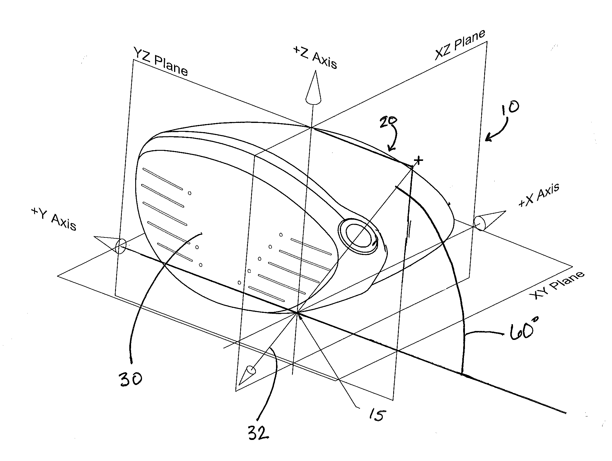
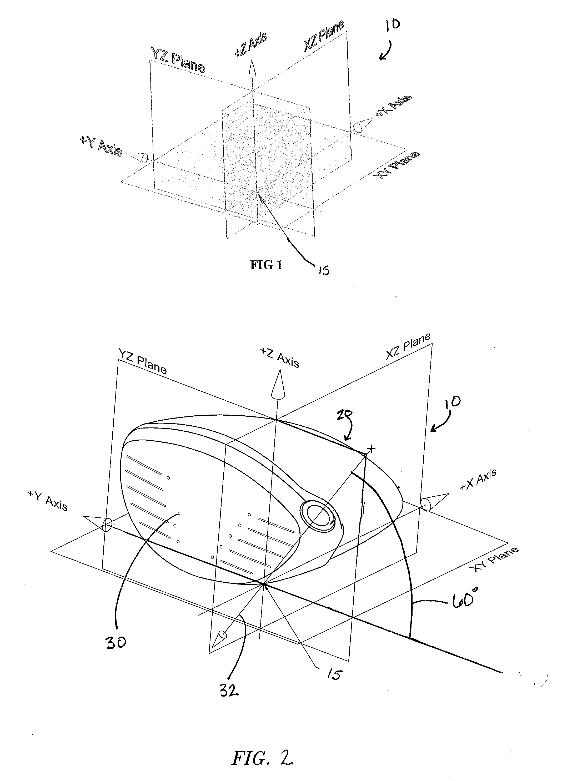
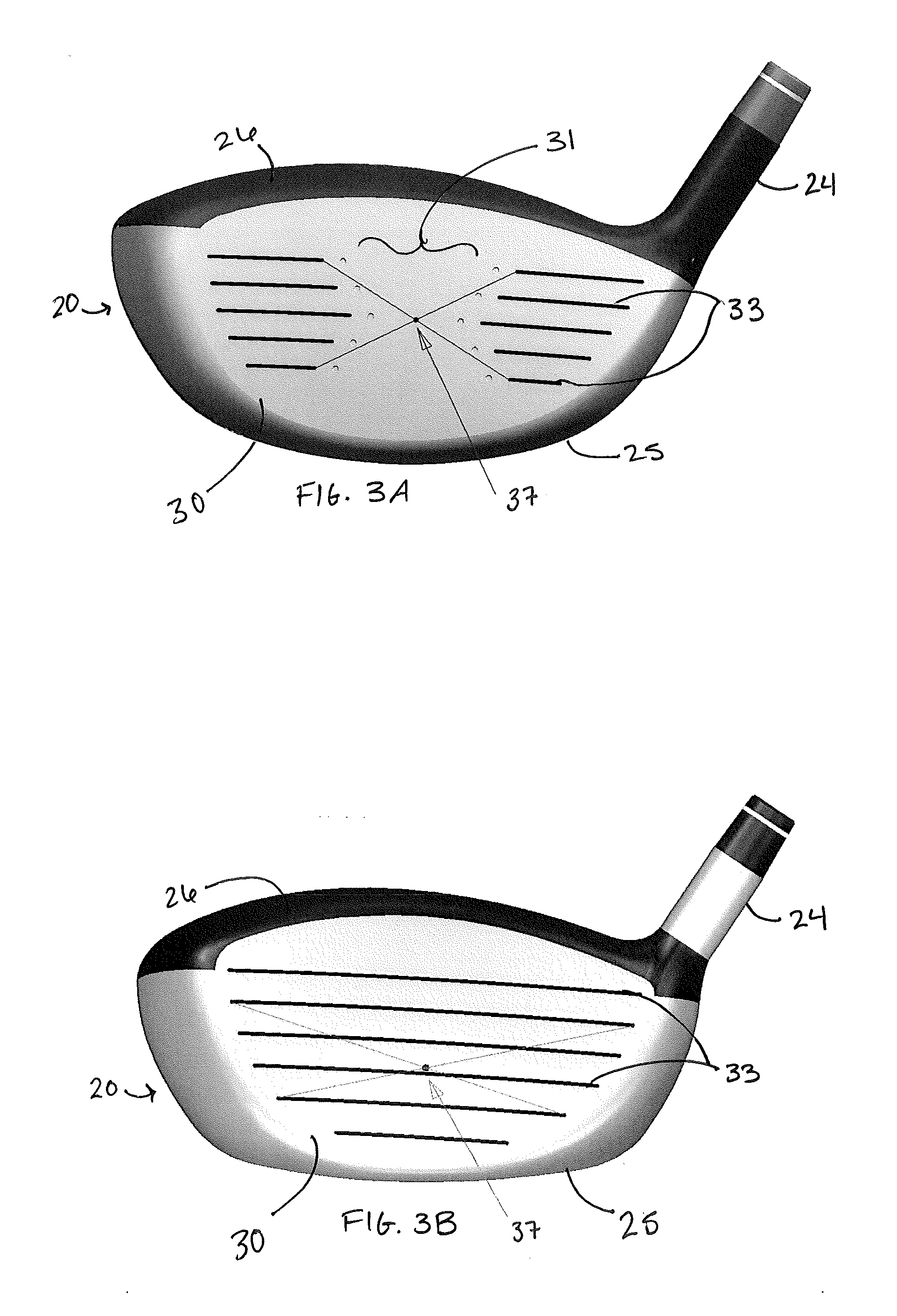
[0031]The present invention relates to design relationships and methods of measurement to achieve an improved aspect ratio of a golf club driver head 20 and an improved golf club driver head 20 crown 26 surface design. The “Largest Tangent Circle Method” (LTCM) was developed to verify the existence of conforming and non-conforming geometries of driver club heads 20.

[0032]In a preferred embodiment of the present invention, the method for forming and / or measuring a driver type golf club head 20 comprises placing the club head 20 into a Cartesian Coordinate System (CCS) 10 comprising an X axis, a Y axis, and a Z axis, all of which intersect at an origin point. Three perpendicular planes, XY, YZ and XZ, exist within the CCS and also intersect at the origin point 15, as shown in FIG. 1. The resulting lines of intersection of the three planes with each other are perpendicular lines representing the CCS, with each line or axis being labeled appropriately X, Y, and Z and passing through the...


PUM

PropertyMeasurementUnit
Angleaaaaaaaaaa
Lengthaaaaaaaaaa
Lengthaaaaaaaaaa

Abstract

Methods of forming a golf club head having improved aerodynamic characteristics are disclosed herein. A preferred method is the largest tangent circle method, which utilizes a Cartesian coordinate system. The method results in identification of the highest point of the crown surface located within a crown apex zone, and this location aids in the design of improved aerodynamic properties of the golf club head.

Description

CROSS REFERENCES TO RELATED APPLICATIONS[0001]This application is a continuation-in-part of U.S. patent application Ser. No. 13 / 023,233, filed on Feb. 8, 2011, which claims priority to U.S. Provisional Patent Application No. 61 / 303,161, filed on Feb. 10, 2010. This application also claims priority to U.S. Provisional Patent Application No. 61 / 365,233, filed on Jul. 16, 2010.STATEMENT REGARDING FEDERALLY SPONSORED RESEARCH OR DEVELOPMENT[0002]Not ApplicableBACKGROUND OF THE INVENTION[0003]1. Field of the Invention[0004]The present invention relates to a method for reducing the effects of drag force when using a driver.[0005]2. Description of the Related Art[0006]The United States Golf Association (USGA) has increasingly limited the performance innovations of golf clubs, particularly drivers. Recently, the USGA has limited the volume, dimensions of the head, such as length, width, and height, face compliance, inertia of driver heads and overall club length. Current methods previously ...

Claims


Application Information

Patent Timeline
IPC IPC(8): B23P15/00
CPCA63B53/0466A63B2053/0408A63B2053/0412Y10T29/49764A63B2059/0011A63B2225/01A63B2053/0437A63B2053/0458A63B60/00A63B53/0408A63B53/0412A63B53/0437A63B53/0458A63B60/006
Inventor EVANS, D. CLAYTONGIBBS, EVAN D.CACKETT, MATTHEW T.EHLERS, STEVEN M.
Owner CALLAWAY GOLF CO
Why Eureka
Try Eureka