Covering panel

a technology of covering panel and spherical plate, which is applied in the field of covering panel, can solve the problems of uneven strength and local differences of plates, particle or even granules of recycled synthetic materials, and the weight of these panels remains too high

Active Publication Date: 2011-10-13
I4F LICENSING NV
View PDF9 Cites 90 Cited by
  • Summary
  • Abstract
  • Description
  • Claims
  • Application Information

AI Technical Summary

Benefits of technology

[0018]According to an important feature of the process, the passage space for the synthetic plate for calibration in this calibration section is designed in such a way that it gradually narrows downstream, e.g. conically from its input slot to its output slot. The height of the output slot between the top surface of the plate and its bottom face at the spot (in the area) of said protruding strips is roughly equal to the thickness T of the plate. At the same time, the passage space at the spot of said intermediate strip-shaped recesses will narrow much less, or hardly at all, or not at all from its input slot to its output slot so that in that area the height (or distance) between the top surface and the bottom of the output slot is slightly bigger than T−C. Thus, passing through the calibration section probably creates a certain slowing down on the bottom faces of the strips protruding from the plate, sliding past and therefore also a gradual transversal thinning of the cooling protruding strips down to the desired roughly constant thickness T and thus beyond the extent of shrinking of the resin due to its cooling down. Furthermore, it is also presumed that this slowing down action can benefit the realization of a smooth and even top surface of the plate in addition to the suction action performed by the partial vacuum equipment, in particular against the top surface of the plate.
[0019]As a consequence of this narrowing or thinning in the calibration section, the still relatively soft excess of synthetic plastic is pressed diagonally upwards away from the protruding strips along their sloped upright edges in the upper wall of the intermediate grooves or recesses. As such, the grooves serve as collection chambers, buffers or compensation chambers for this pressed-away synthetic material against their upper wall. As a result of this, the upper wall of the groove—i.e. in the area of the small base of the trapezium-shaped cross-section of the groove—becomes less flat and less even. This, however, is not inconvenient since the groove is on the inside of the wall covering. Thus, the depth C of the grooves is in reality an average depth as a result of any irregularities in their upper wall. In contrast, the thickness T of the protruding strips should remain and indeed remain the same and constant over all plates to be linked to each other, due to these compensation chambers. Otherwise the surface of the wall covering might show an impermissible difference in level e.g. with adjacent panel edges.

Problems solved by technology

Nonetheless, the weight of these panels remains too high.
However, the application of at least a considerable portion of recycled synthetic materials, e.g. recycled PVC in the synthetic materials, creates the risk of obtaining plates with uneven strength and local differences of other characteristics spread over their volume.
However, these particles or even granules of recycled synthetic material, as starting material to use, do not all have the same composition and characteristics.
Furthermore, post-consumptive recycling material often contains an extra tarnishing with the presence of foreign particles, or—for example due to ageing—the properties of the polymer sensitively deviate from new, freshly prepared polymers.
This can result in varying flow patterns and / or flow rate fluctuations in the molten mass by the supply to, and passage through, the extrusion nozzles and during the passage of the cooling molten mass into the adjacent cooled calibration section.
In this way it becomes difficult to continuously realize a sufficiently and evenly dense filling over the entire width of the passage opening of the extrusion nozzle and in particular to produce a support plate with an even and flat top surface.
Thus, the panel thickness cannot be reduced to below a limit whereby the connection or coupling strength of said tongue between the groove edges would become insufficient.
Nonetheless, the need for extremely thin panels or tiles remains, while the strength of the tongue-in-groove connection, according to EP 1808546, possibly no longer suffices and for which another connection configuration would have to be applied.
Moreover, when using thinner panels, the need to subsequently disconnect them from the assembled or installed wall-covering to replace them or to disassemble and reuse the covering elsewhere, remains.

Method used


Image

  • Covering panel
  • Covering panel
  • Covering panel

Examples


Embodiment Construction

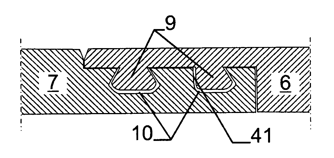
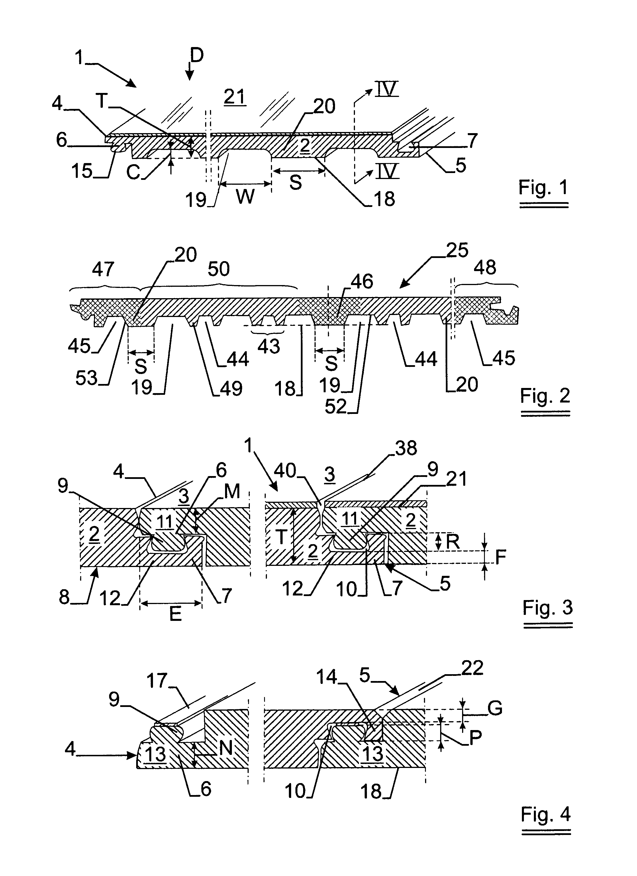
[0035]The covering panel 1 according to the figure shows a preferred embodiment according to the invention for very thin panels with an extruded support plate 2, made from synthetic plastic material and generally with a commonly known waterproof, decorative and wear-resistant protective coating 21. These panels can have a total T thickness of 3 to 6 mm. The support plates 2 have a flat and usually a rectangular or square top surface 3. On the pair of opposite lengthwise sides 4, respectively 5 a male profile edge 6, respectively a complementary female profile edge 7 is produced, either simultaneously during the extrusion of the plate 2 or only afterwards by means of a milling process on plate edges that were not profiled during the extrusion. If so desired, profile edges 6, 7 preformed during extrusion can be finished more precisely by means of a suitable milling process afterwards.

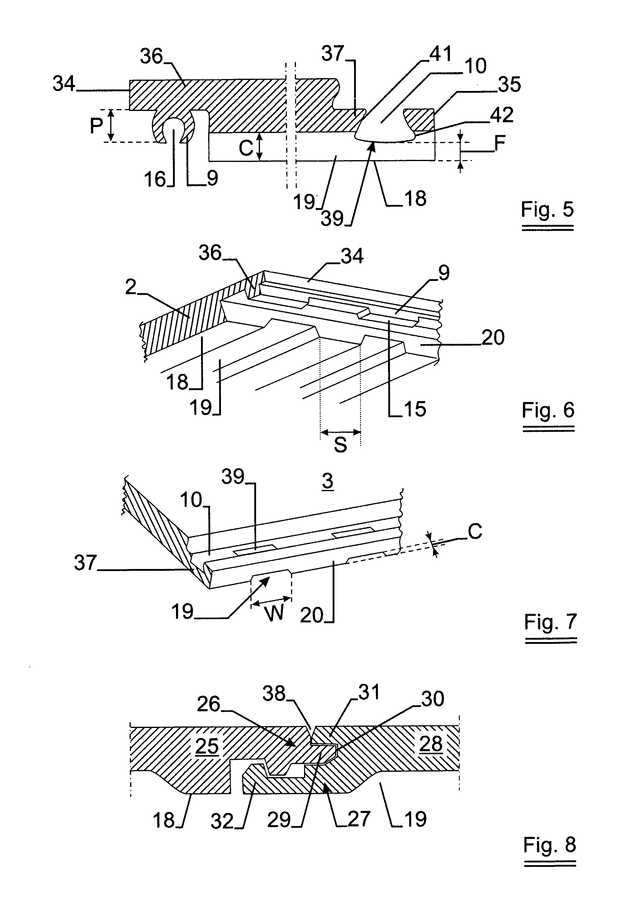
[0036]By milling, the male profile edge 36, respectively the complementary female profile edge 37, are...


PUM

PropertyMeasurementUnit
thicknessaaaaaaaaaa
thicknessaaaaaaaaaa
thicknessaaaaaaaaaa

Abstract

A covering panel has a support plate, made from synthetic plastic material, with a flat and even top surface, a bottom face and pairs of opposite sides provided with complementary profile edges in the form of a male profile edge on one side and a female profile edge on the other, where said male profiled edge can be connected to a female edge of an equal adjacent covering panel, preferably according to a direction that runs perpendicular to said top surface. In their bottom face there are strip-shaped recesses that run according to the direction of extrusion and alternate with a number of support strips, of which at least a part has a width S along that bottom face that complies with 1.5 T<S<10 T, and whereby 0.4 T<C<0.7 T applies, in which C is the average depth of these recesses. A process extrudes a synthetic plastic plate.

Description

[0001]The invention concerns a covering panel; in particular a wall-covering panel with an extruded support plate made from synthetic plastic material and which panel is impermeable. Within this context the term wall-covering pertains to, amongst others, coverings for walls, on floors, ceilings, furniture surfaces and in particular to a floating covering for waterproof floors.BACKGROUND OF THE INVENTION[0002]A waterproof floor covering of this type is known from EP 1808546 of the applicant. In consideration of the increasingly stricter ecological requirements or motivations for saving materials, weight and energy, amongst others, the need arises for thinner panels, yet still with sufficient strength and shape retention and with sufficiently strong coupling or connecting elements at their edges of the panels or tiles with adjacent panels or tiles. In the relatively thick core layer of the extruded panels, according to EP 1808546, closed air channels have previously been created. None...

Claims


Application Information

Patent Timeline
Patent Type & Authority Applications(United States)
IPC IPC(8): E04C2/38B29C47/88B29C47/06E04C2/20B29C48/07
CPCB29C47/0019B29C66/435B29C47/0057B29C47/065B29C47/128B29C47/145B29C47/90B29C53/04B29C65/58B29C66/02245B29C66/1122B29C66/1142B29C66/43B29C2791/006B29C2793/0027B29K2023/00B29K2025/00B29K2027/06B29K2031/04B29K2067/00B29K2077/00B29K2105/0008B29K2105/26B29K2201/00B29K2995/0069B29L2007/002B29L2009/00B29L2016/00B29L2031/003B29L2031/10B29L2031/44B29L2031/732B29L2031/738B29L2031/772B29L2031/776E04C2/20E04F13/18E04F15/10E04F2201/0138E04F2201/0146E04F2201/0153E04F2201/041E04F2201/042B29C47/003B29C65/00B29C66/12421B29C66/12423B29C66/1282B29C66/12841B29C66/14B29C66/71B29C66/72343B29C48/07B29C48/12B29C48/0018B29C48/21B29C48/304B29C48/307B29C48/916B29C48/90B29C48/904B29C48/908Y02W30/62B29K2033/08B29K2027/16B29K2027/08B29K2025/06B27N3/28
Inventor WYBO, CARLOSSAMMY, LASSEEL
Owner I4F LICENSING NV
Why Eureka
Try Eureka