
Front electrode for solar cell having minimized power loss and solar cell containing the same

Inactive Publication Date: 2011-10-13
LG CHEM LTD
View PDF4 Cites 29 Cited by
  • Summary
  • Abstract
  • Description
  • Claims
  • Application Information

AI Technical Summary

Benefits of technology

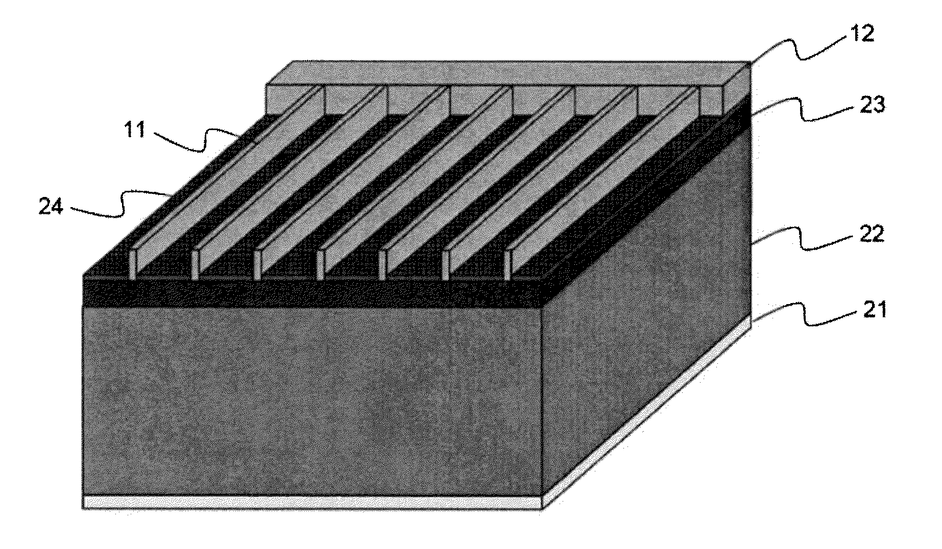
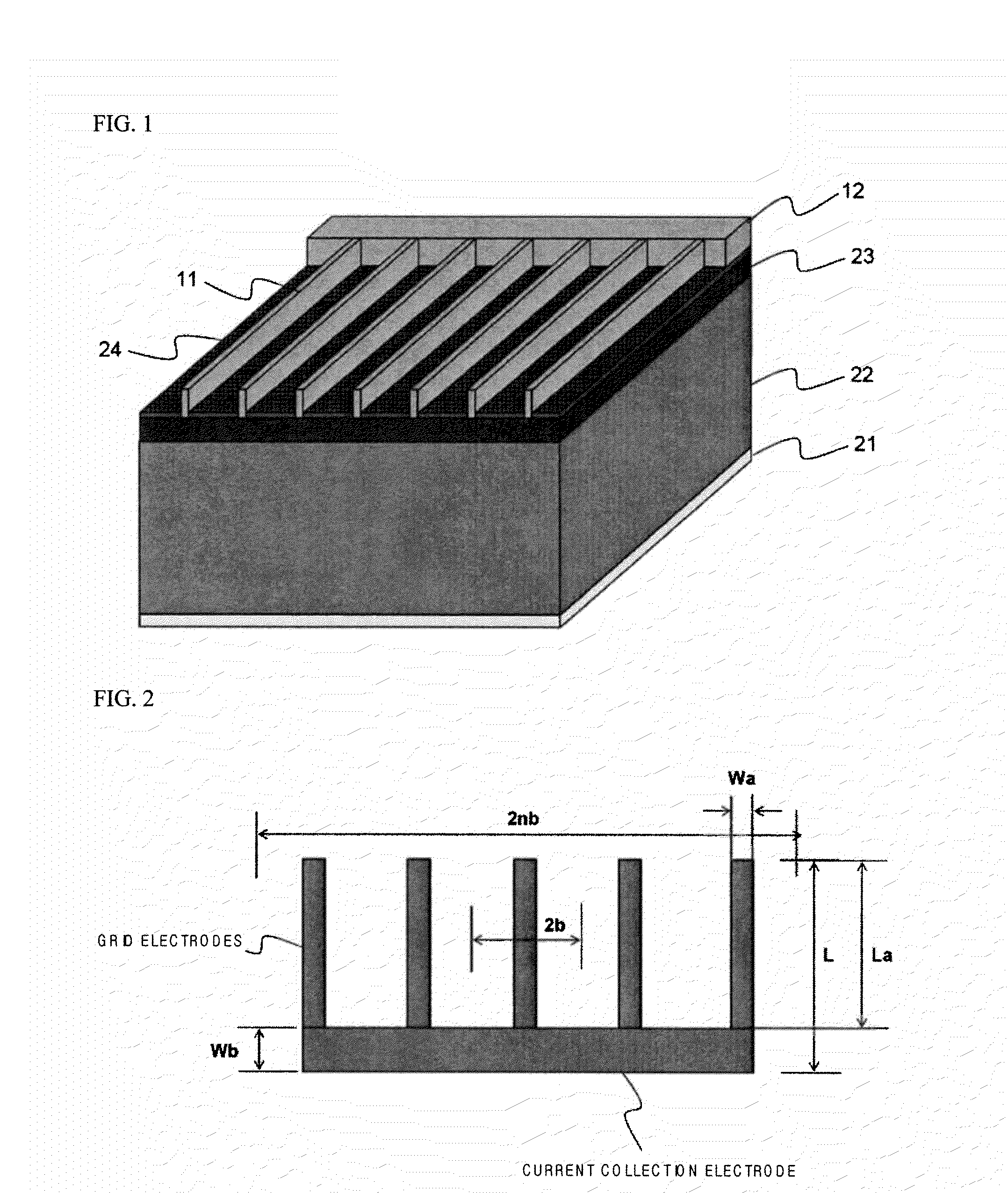
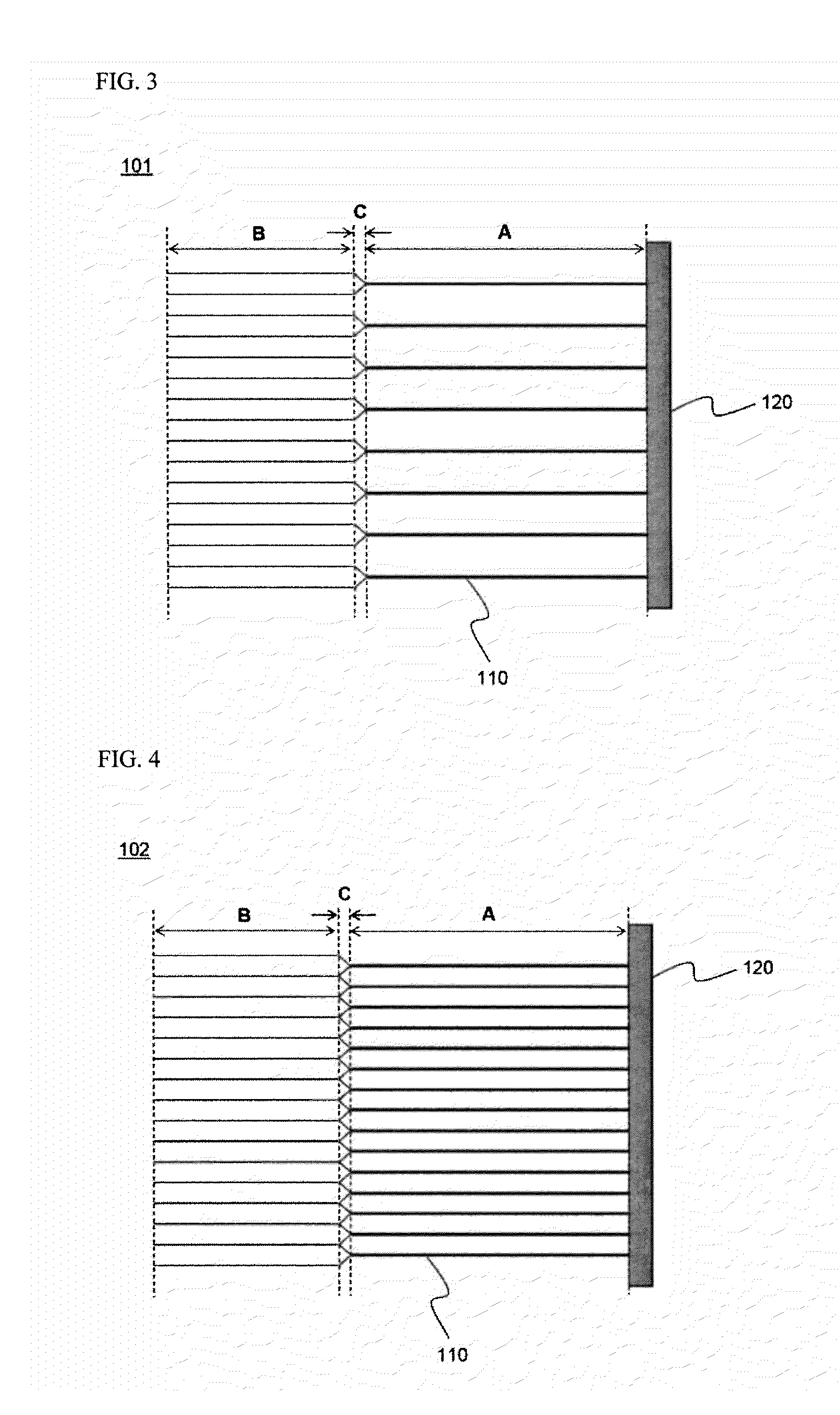
[0012]Specifically, it is an object of the present invention to provide a front electrode for solar cells wherein the width of grid electrodes is adjusted to minimize power loss caused by the electrodes and maximize light absorption.
[0056]It is also possible to print a pattern having a sub-micrometer size using the gravure printing method. Consequently, the gravure printing method has an advantage of suitably forming a micrometer scale pattern and of simultaneously patterning a large area in the same manner as the offset printing method.

Problems solved by technology

Loss may include loss caused by light reflected from a surface, loss caused by recombination of a carrier at the surface or an electrode interface, loss caused by recombination of the carrier in a solar cell, and loss caused by internal resistance of the solar cell.
Power loss caused by electrodes may include resistance loss caused by movement of light current at an n-type semiconductor layer, loss caused by contact resistance between the n-type semiconductor layer and grid electrodes, resistance loss caused by photoelectric current flowing in the grid electrodes, and loss caused by an area covered by the grid electrodes.

Method used


Image

  • Front electrode for solar cell having minimized power loss and solar cell containing the same
  • Front electrode for solar cell having minimized power loss and solar cell containing the same
  • Front electrode for solar cell having minimized power loss and solar cell containing the same

Examples


example 2

[0088]A solar cell having a resistance of 100 ohm at an n layer was manufactured using the same method as in Example 1 except that the grid electrodes of the first pattern part were formed to have a length of 2.4 cm, the grid electrodes of the second pattern part were formed to have a length of 1.2 cm, the grid electrodes of the first pattern part were formed to have a width of 20 μm and intervals of 0.83 mm, and the dendrite electrodes C were formed to have a length of 0.05 cm.

experimental example 1

[0093]Power losses of the solar cells manufactured according to Examples 1 and 2 and Comparative examples 1 to 4 were calculated. The results are indicated in FIGS. 9 and 10 and Table 2 below.

TABLE 2DifferenceDifferenceof loss fromof loss fromn-typeContactFingerShadowTotalComparativeComparativelosslosslosslosslossexample 1 (3)example 2 (4)Example 10.160.0030.310.671.140.21%0.79%Example 20.210.0030.350.701.260.41%0.68%Comparative0 / 320.0030.180.941.35——example 1Comparative 0.0070.0050.950.981.93——example 2Comparative0.280.0030.121.261.67——example 3Comparative0.010.00070.950.981.94——example 4

[0094]In Table 2, the n-type loss (loss I) is caused when current flows in the n-type semiconductor layer, the contact loss (loss II) is caused when the current flows from the n-type semiconductor layer to the grid electrodes, the finger loss (loss III) is caused when the current flows in the grid electrodes, and the shadow loss (loss IV) is caused by an area covered by the grid electrodes.

[0095]Al...


PUM


Abstract

Disclosed herein is a front electrode for solar cells, wherein the front electrode is configured in a structure in which a pattern including a plurality of grid electrodes arranged in parallel and at least one current collection electrode intersecting the grid electrodes is formed on a semiconductor substrate, current introduced to the grid electrodes is moved to and collected in the current collection electrode, and the width of each of the grid electrodes is increased toward the current collection electrode.

Description

TECHNICAL FIELD[0001]The present invention relates to a front electrode for solar cells having minimized power loss and a solar cell including the same, and, more particularly, to a front electrode for solar cells, wherein the front electrode is configured in a structure in which a pattern including a plurality of grid electrodes arranged in parallel and at least one current collection electrode intersecting the grid electrodes is formed on a semiconductor substrate, current introduced to the grid electrodes is moved to and collected in the current collection electrode, and the width of each of the grid electrodes is increased toward the current collection electrode.BACKGROUND ART[0002]In recent years, with increased concerns about environmental problems and depletion of nonrenewable energy sources, solar cells have drawn attention as an alternative energy source which uses abundant energy resources, is free of problems associated with pollution and has high energy efficiency.[0003]...

Claims


Application Information

Patent Timeline
IPC IPC(8): H01L31/0224
CPCY02E10/52H01L31/022433Y02E10/50H01L31/0224H01L31/04
Inventor YOON, SEOKHYUNHWANG, INSEOKKIM, SEUNG WOOK
Owner LG CHEM LTD
Learn More