Induction heat treatment of an annular workpiece

a technology of induction heat treatment and annular workpiece, which is applied in the direction of heat treatment apparatus, electric/magnetic/electromagnetic heating, furnaces, etc., can solve the problems of reducing requiring high-power induction heating sources, and a large amount of power. achieve the effect of enhancing the metallurgical uniformity of the annular workpi

Active Publication Date: 2011-10-13
INDUCTOHEAT INC
View PDF7 Cites 31 Cited by
  • Summary
  • Abstract
  • Description
  • Claims
  • Application Information

AI Technical Summary

Benefits of technology

[0013]In one aspect the present invention is a method of, and apparatus for, scan induction heat treatment of an annular workpiece where at least two inductors are simultaneously used. Controlled movement of the inductors and application of quenchant is provided at the in

Problems solved by technology

One of the main drawbacks of a single-shot heat treatment is the necessity of supplying the induction coil (inductor) with a substantial amount of power since the simultaneous heating method requires a magnitude of power sufficient to raise the temperature of the entire surface of the ring to the required level at required depth.
Therefore costly high power induction heating sources are required.
A disadvantage of this method is the presence of a “soft” zone 90d in the metallurgically hardened (shaded) penetration depth 90c′ as shown in FIG. 2(b) where the workpiece will not be properly heat treated.
At the start of the heating process, the distance between inductors 103a and 103b can not be immediately adjacent to each other since the magnetic fields established by current flow in each inductor could interfere with each other if supplied by independent power supplies, which can result in lower levels of induced heating.
If quenchant is supplied too soon (that is, when the inductors have not traveled sufficiently far apart from each other), quenchant can sp

Method used


Image

  • Induction heat treatment of an annular workpiece
  • Induction heat treatment of an annular workpiece
  • Induction heat treatment of an annular workpiece

Examples


Embodiment Construction

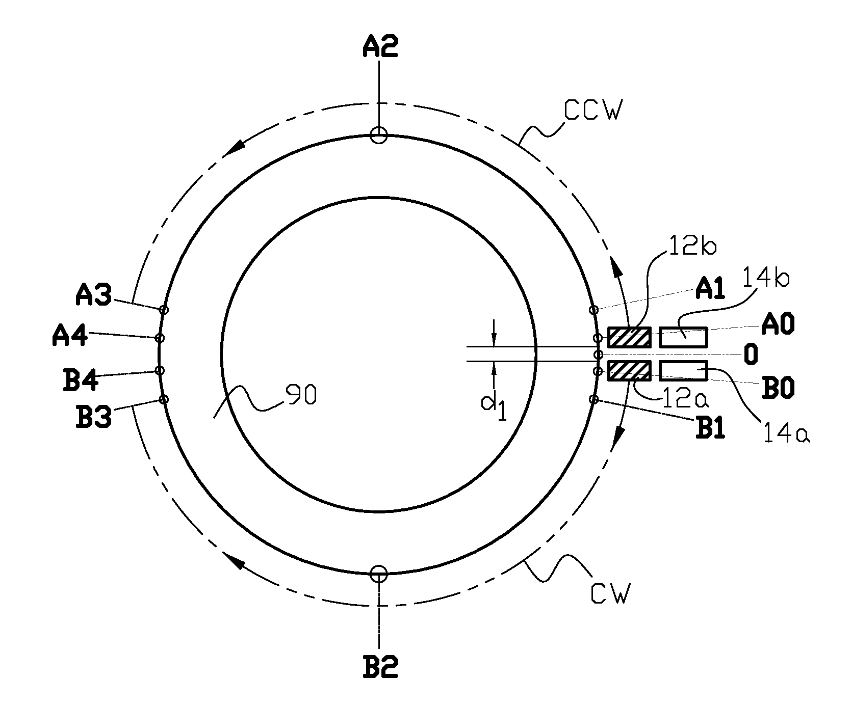
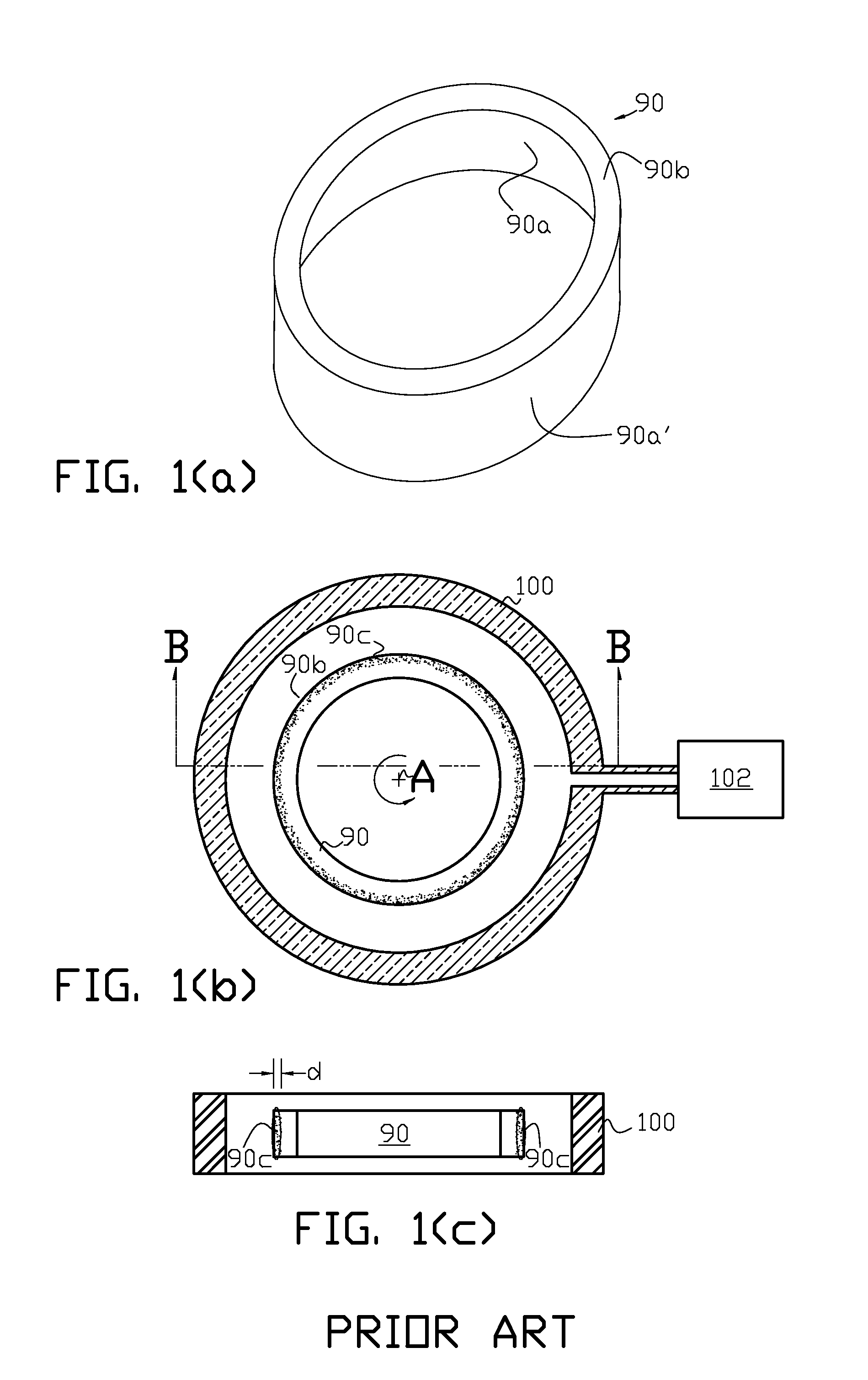
[0031]The term annular (ring) workpiece is used to describe an annular component, such as, but not limited to, a large roller or ball bearing race. Such bearing races can be used, for example, in thrust bearings in wind turbines that are capable of producing electric power in the megawatt range. If the workpiece is a large bearing race, the surface, or surfaces that may be induction heat treated are the inner and outer circular races (90a and 90a′ respectively in FIG. 1(a)) and axial races (90b in FIG. 1(a); lower axial race not visible). The relative term “large” is used herein to describe an annular workpiece sufficiently large to be affected by the deficiencies described above for the prior art dual inductor scan induction heat treatment process; such an annular workpiece typically has an inside diameter of approximately one meter or larger.

[0032]An example of the induction metallurgical heat treatment process of the present invention is illustrated in FIG. 6(a) through FIG. 7(f)...


PUM

PropertyMeasurementUnit
Lengthaaaaaaaaaa
Angleaaaaaaaaaa
Poweraaaaaaaaaa

Abstract

Apparatus and method are provided for inductively heat treating a circular surface of annular workpieces where at least one inductor pair is used to perform a scan induction heat treatment of the circular surface. Controlled movement of the inductors and application of quenchant is provided particularly at the initial and final heat treatment locations on the circular surface to enhance metallurgical uniformity of the annular workpiece at these locations. In combination with controlled movement of the inductors, a simultaneous power-frequency control scheme can be applied to the inductors during the heat treatment process.

Description

CROSS REFERENCE TO RELATED APPLICATIONS[0001]This application claims the benefit of U.S. Provisional Patent Application Ser. No. 61 / 323,428 filed Apr. 13, 2010, hereby incorporated herein by reference in its entirety.FIELD OF THE INVENTION[0002]The present invention generally relates to induction heat treatment of annular workpieces, and in particular to when at least one pair of inductors are utilized in a scan induction heat treatment process of one or more surfaces of an annular workpiece.BACKGROUND OF THE INVENTION[0003]Electric induction heating can be used to heat electrically conductive materials (for example, cast irons and steels) to temperatures in the austenitic range. The heated material is then quenched to temperatures where low transformation products, such as martensite and / or bainite are formed. There are two basic approaches to inductively heating a large annular, or ring-shaped workpiece, namely a single-shot (static) process or a scan process.[0004]In a static ind...

Claims


Application Information

Patent Timeline
IPC IPC(8): H05B6/10
CPCC21D1/10H05B6/101C21D9/40C21D1/667C21D1/42C21D9/08C22C37/00C22C38/00H05B6/40Y02P10/25H05B6/02H05B6/10H05B6/06
Inventor DOYON, GARY A.ANDRA, FRANKBROWN, DOUGLAS R.LOVELESS, DON L.RUDNEV, VALERY I.
Owner INDUCTOHEAT INC
Why Eureka
Try Eureka