Dielectric resonator antenna embedded in multilayer substrate for enhancing bandwidth

a technology of dielectric resonator antenna and multi-layer substrate, which is applied in the direction of antennas, antenna details, electrical equipment, etc., can solve the problems of reducing affecting the service life of the antenna, so as to reduce the variation in antenna characteristics, improve the service life, and facilitate manufacturing

Active Publication Date: 2011-10-13
SAMSUNG ELECTRO MECHANICS CO LTD
View PDF10 Cites 65 Cited by
  • Summary
  • Abstract
  • Description
  • Claims
  • Application Information

AI Technical Summary

Benefits of technology

[0017]Accordingly, the present invention has been made keeping in mind the above problems occurring in the prior art, and the present invention is intended to provide a dielectric resonator antenna embedded in a multilayer substrate for enhancing bandwidth, in which a multilayer substrate manufacturing process is implemented as a single manufacturing process, thus enabling a dielectric resonator antenna to be easily manufactured and minimizing variations in antenna characteristics depending on fabrication errors.
[0018]Further, the present invention is intended to provide a dielectric resonator antenna embedded in a multilayer substrate for enhancing bandwidth, which can minimize the deformation of radiation patterns attributable to multiple resonances while ensuring a wider bandwidth by means of multiple resonances.

Problems solved by technology

Accordingly, fabrication errors occur, and thus a problem may arise from the standpoint of the reliability of products.
In a multilayer structure environment such as in LTCC and LCP manufacturing processes, a patch antenna having planar characteristics is mainly used, but has a disadvantage of a narrow bandwidth of about 5%.
However, when the conventional multi-resonance technique is used, differences may occur between the radiation patterns of an antenna at individual resonant frequencies, and variations in the characteristics of the antennas depending on fabrication errors in the multi-resonance antenna may be greater than in a single-resonance antenna.
The conventional dielectric resonator antenna is frequently used to overcome the disadvantages of the conventional patch antenna, but it requires a separate dielectric resonator disposed outside a substrate, and thus there is the inconvenience of manufacturing processes compared to a stacked patch antenna implemented using a single manufacturing process.
In contrast, such a dielectric resonator antenna is disadvantageous in that the to radiation patterns thereof are deformed within the bandwidth.

Method used


Image

  • Dielectric resonator antenna embedded in multilayer substrate for enhancing bandwidth
  • Dielectric resonator antenna embedded in multilayer substrate for enhancing bandwidth
  • Dielectric resonator antenna embedded in multilayer substrate for enhancing bandwidth

Examples


Embodiment Construction

[0067]Hereinafter, embodiments of the present invention will be described in detail with to reference to the attached drawings.

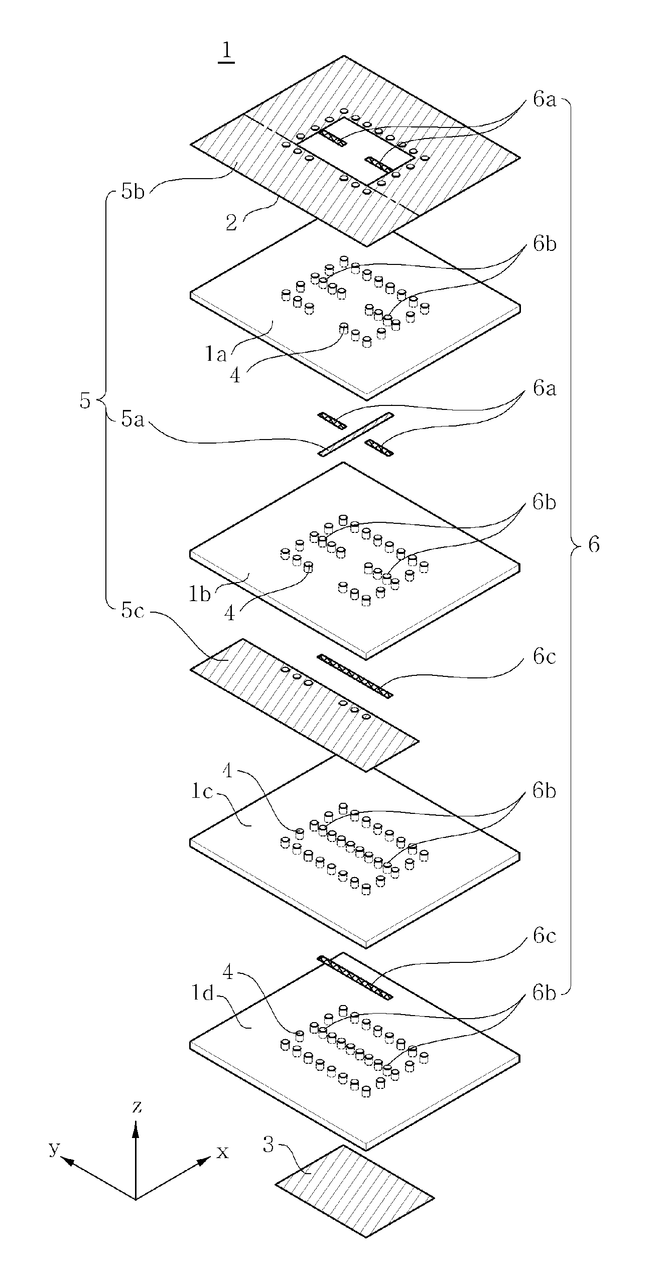
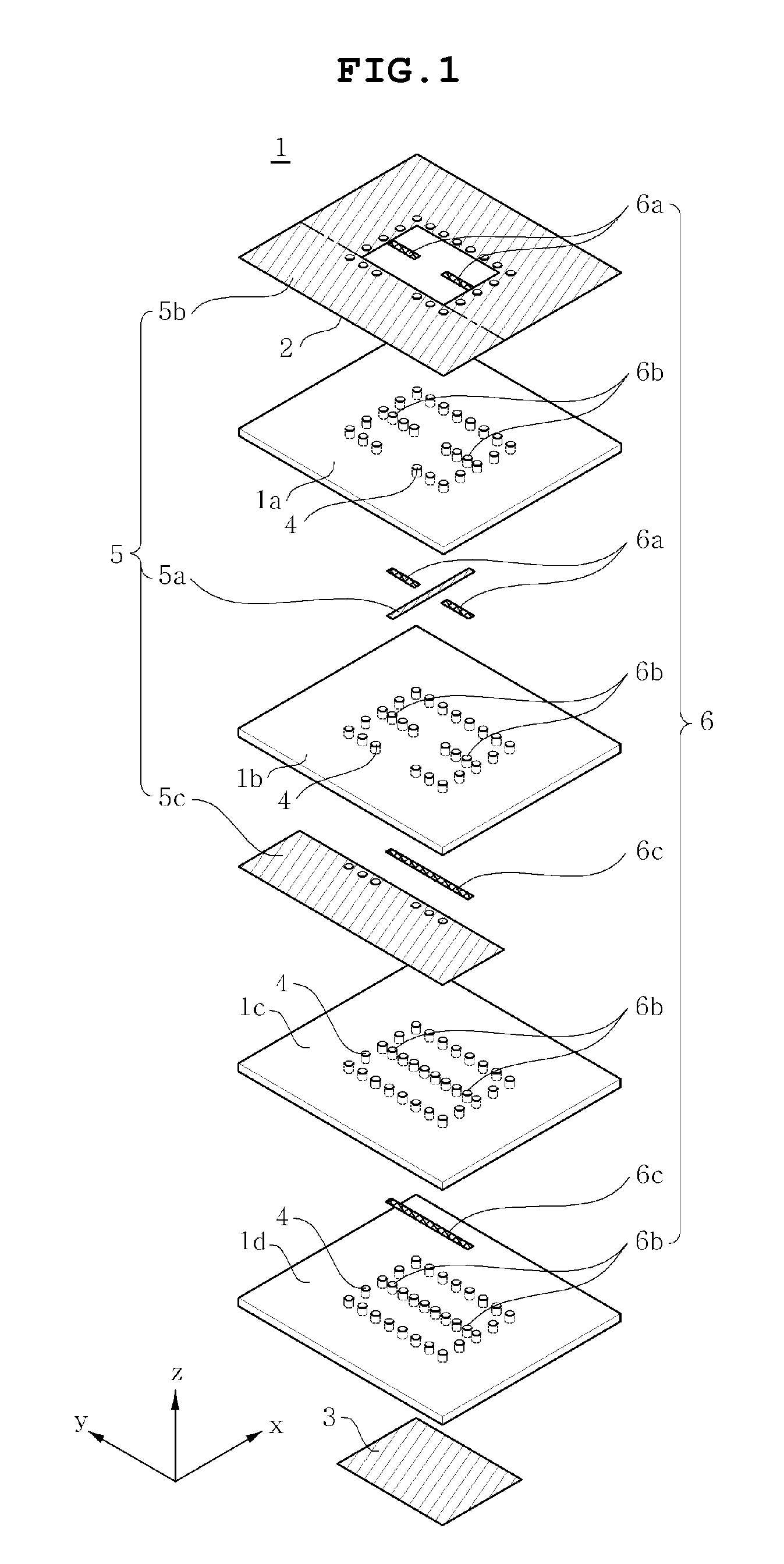
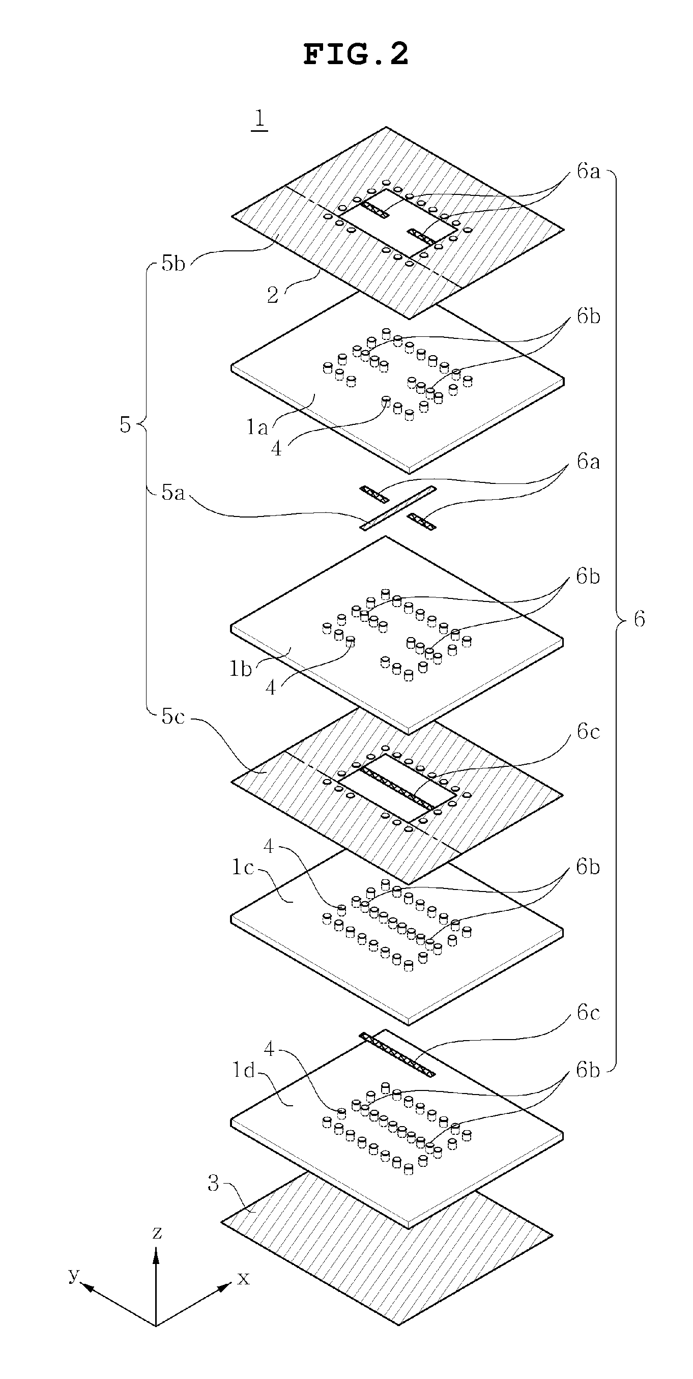
[0068]For convenience of description, a multilayer substrate 1 according to the present invention is implemented as a substrate in which four insulating layers are stacked one on top of one another, but the multilayer substrate of the present invention is not limited to this structure.

[0069]Further, it should be noted that conductive layers other than conductive layers required for a feeding part are considered to be omitted and are not shown in the drawings of the present invention.

[0070]FIGS. 1 and 2 are exploded perspective views of a dielectric resonator antenna embedded in a multilayer substrate for enhancing bandwidth according to embodiments of the present invention, FIG. 3 is a top view of the dielectric resonator antenna of FIG. 1, FIG. 4 is a sectional view of the dielectric resonator antenna of FIG. 1 taken along line A-A′ ofFIG. 3, and FIG. 5 is ...


PUM


Abstract

Disclosed herein is a dielectric resonator antenna embedded in a multilayer substrate for enhancing bandwidth. The dielectric resonator antenna includes a multilayer substrate, a first conductive plate, a second conductive plate, a plurality of first metal via holes, a feeding part configured to feed a dielectric resonator, and a conductive pattern part inserted into the dielectric resonator so that a vertical metal interface is formed in the dielectric resonator. Accordingly, the dielectric resonator antenna has low sensitivity to fabrication errors and an external environment, and can enhance the radiation characteristics of the antenna when multiple resonances occur.

Description

CROSS REFERENCE TO RELATED APPLICATION[0001]This application claims the benefit of Korean Patent Application No. 10-2010-0033998, filed on Apr. 13, 2010, entitled “Dielectric Resonant Antenna Embedded in Multilayer Substrate for Enhancing Bandwidth”, which is hereby incorporated by reference in its entirety into this application.BACKGROUND OF THE INVENTION[0002]1. Technical Field[0003]The present invention relates generally to a dielectric resonator antenna embedded in a multilayer substrate for enhancing bandwidth.[0004]2. Description of the Related Art[0005]Mainly, products for a conventional transmission / reception system have been constructed by assembling individual parts into each system. However, research into System On Package (SOP) products in which a millimeter-wave band transmission / reception system is implemented as a single package has recently been conducted, and some products have been commercialized.[0006]Technology related to SOP products has been developed along wit...

Claims


Application Information

Patent Timeline
Patent Type & Authority Applications(United States)
IPC IPC(8): H01Q9/04
CPCH01Q1/2283H01Q9/0485H01Q1/38
Inventor LEE, JUNG AUNPARK, CHUL GYUNKIM, MOONILLEE, KOOK JOO
Owner SAMSUNG ELECTRO MECHANICS CO LTD
Why Eureka
Try Eureka